73S1215F Data Sheet
DS_1215F_003
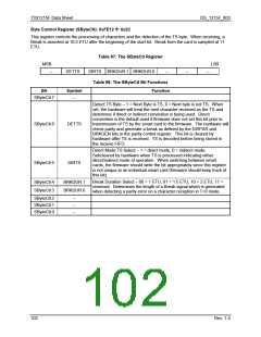
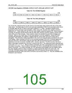
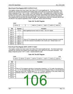
Block Guard Time Register (BGT): 0xFE16 Å 0x10
This register contains the Extra Guard Time Value (EGT) most-significant bit. The Extra Guard Time
indicates the minimum time between the leading edges of the start bit of consecutive characters. The
delay is depends on the T=0/T=1 mode. Used in transmit mode. This register also contains the Block
Guard Time (BGT) value. Block Guard Time is the minimum time between the leading edge of the start
bit of the last character received and the leading edge of the start bit of the first character transmitted.
This should not be set less than the character length. The transmission of the first character will be held
off until BGT has elapsed regardless of the TX data and TX/RX control bit timing.
Table 105: The BGT Register
MSB
EGT.8
LSB
BGT.0
–
–
BGT.4
BGT.3
BGT.1
BGT.2
Bit
Symbol
Function
Most-significant bit for 9-bit EGT timer. See EGT below.
BGT.7
BGT.6
BGT.5
BGT.4
BGT.3
BGT.2
BGT.1
BGT.0
EGT.8
–
–
BGT.4
BGT.3
BGT.2
BGT.1
BGT.0
Time in ETUs between the start bit of the last received character to start bit
of the first character transmitted to the smart card. Default value is 22.
Extra Guard Time Register (EGT): 0xFE17 Å 0x0C
This register contains the Extra Guard Time Value (EGT) least-significant byte. The Extra Guard Time
indicates the minimum time between the leading edges of the start bit of consecutive characters. The
delay is depends on the T=0/T=1 mode. Used in transmit mode.
Table 106: The EGT Register
MSB
EGT.7
LSB
EGT.0
EGT.6
EGT.5
EGT.4
EGT.3
EGT.1
EGT.2
Bit
Function
EGT.7
EGT.6
EGT.5
EGT.4
EGT.3
EGT.2
EGT.1
EGT.0
Time in ETUs between start bits of consecutive characters. In T=0 mode, the minimum is
1. In T=0, the leading edge of the next start bit may be delayed if there is a break detected
from the smart card. Default value is 12. In T=0 mode, regardless of the value loaded, the
minimum value is 12, and for T=1 mode, the minimum value is 11.
106
Rev. 1.4

 TERIDIAN [ TERIDIAN SEMICONDUCTOR CORPORATION ]