Two-chip MicroCapacitance (MC) SIDACtor Device
Two-chip MicroCapacitance (MC)
SIDACtor Device
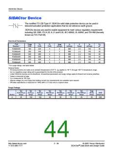
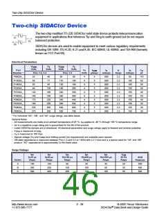
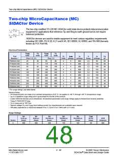
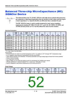
The two-chip modified TO-220 MC SIDACtor solid state device protects telecommunication
1
equipment in applications that reference Tip and Ring to earth ground but do not require
(T)
2
(G)
balanced protection.
3
(R)
SIDACtor devices are used to enable equipment to meet various regulatory requirements
including GR 1089, ITU K.20, K.21 and K.45, IEC 60950, UL 60950, and TIA-968 (formerly
known as FCC Part 68).
Electrical Parameters
VDRM
VS
VDRM
Volts
VS
Volts
Volts
Volts
Part
VT
IDRM
IS
IT
IH
CO
pF
Number *
Pins 1-2, 3-2
Pins 1-3
Volts
µAmps
mAmps
Amps
mAmps
P0602AC MC
P1402AC MC
P1602AC MC
P2202AC MC
P2702AC MC
P3002AC MC
P3602AC MC
P4202AC MC
P4802AC MC
P6002AC MC
25
58
65
40
77
95
130
160
180
220
250
300
350
50
80
4
4
4
4
4
4
4
4
4
4
5
5
5
5
5
5
5
5
5
5
800
800
800
800
800
800
800
800
800
800
2.2
2.2
2.2
2.2
2.2
2.2
2.2
2.2
2.2
2.2
50
60
60
60
50
50
50
40
40
40
40
116
130
180
240
280
340
380
440
550
154
190
260
320
360
440
500
600
700
150
150
150
150
150
150
150
150
150
90
120
140
170
190
220
275
* For surge ratings, see table below.
General Notes:
•
•
•
•
•
•
•
All measurements are made at an ambient temperature of 25 °C. IPP applies to -40 °C through +85 °C temperature range.
I
PP is a repetitive surge rating and is guaranteed for the life of the product.
Listed SIDACtor devices are bi-directional. All electrical parameters and surge ratings apply to forward and reverse polarities.
V
DRM is measured at IDRM.
VS is measured at 100 V/µs.
Special voltage (VS and VDRM) and holding current (IH) requirements are available upon request.
Off-state capacitance is measured between Pins 1-2 and 3-2 at 1 MHz with a 2 V bias.
Surge Ratings
IPP
IPP
IPP
IPP
IPP
ITSM
60 Hz
Amps
2x10 µs
8x20 µs
10x160 µs
10x560 µs
10x1000 µs
di/dt
Series
Amps
Amps
Amps
Amps
Amps
Amps/µs
C
500
400
200
150
100
50
500
http://www.teccor.com
+1 972-580-7777
2 - 30
© 2002 Teccor Electronics
SIDACtor Data Book and Design Guide
®

 TECCOR [ TECCOR ELECTRONICS ]