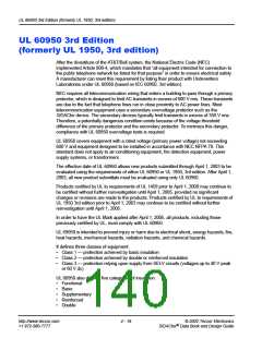
ITU-T K.20 and K.21
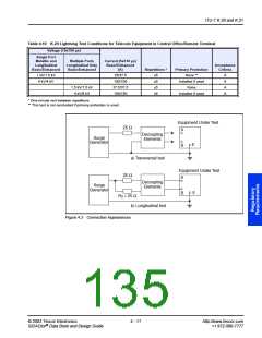
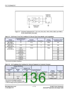
Equipment
Under Test
R
R
A
U
a.c.
E
B
Timing Circuit
Generator
Figure 4.4 Connection Appearances (R = 10 ꢀ, 20 ꢀ, 40 ꢀ, 80 ꢀ, 160 ꢀ, 300 ꢀ, 600 ꢀ, and 1000 ꢀ
for the various power cross tests)
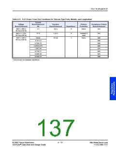
Table 4.11 K.20 Power Cross Test Conditions for Telecom Type Ports, Metallic, and Longitudinal
Current (5x310 µs)
Voltage
Basic/Enhanced
Duration
Primary
Acceptance Criteria
Basic/Enhanced
(A)
Basic/Enhanced
Repetitions *
Protection
Basic/Enhanced
600 V/600 V
1/1
0.2 s
1 s/2 s
15 min
5
None
None
None
A/A
A/A
50 Hz or 60 Hz
600/1.5 kV
1/7.5
5
1
50 Hz or 60 Hz
230/230 V
23/23
11.5/11.5
5.75/5.75
2.875/2.875
1.44/1.44
0.77/0.77
0.38/0.38
0.23/0.23
B/B
B/B
B/B
B/B
B/A
B/A
B/A
B/B
50 Hz or 60 Hz
* One-minute rest between repetitions
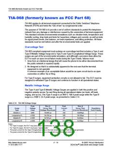
Table 4.12 K.21 Lightning Test Conditions for Telecom Equipment on Customer Premises
Voltage (10x700 µs)
Single Port
Multiple Ports
Longitudinal
Metallic
Longitudinal Only Current (5x310 µs)
(kV)
(kV)
(kV)
Basic/Enhanced
(A)
Primary
Acceptance
Criteria
Basic/Enhanced Basic/Enhanced Basic/Enhanced
Repetitions *
Protection
None
1.5/6 **
4/6
37.5/150
100/150
37.5/37.5
100/150
±5
±5
±5
±5
A ***
A
A ***
A
Installed if used
None
Installed if used
1.5/1.5
4/6
1.5/1.5
4/6
* One-minute rest between repetitions
** Reduce to 1.5 kV if SPD connects to GRD.
*** Does not apply if primary protectors are used.
http://www.teccor.com
+1 972-580-7777
4 - 12
© 2002 Teccor Electronics
SIDACtor Data Book and Design Guide
®

 TECCOR [ TECCOR ELECTRONICS ]