TIA-968 (formerly known as FCC Part 68)
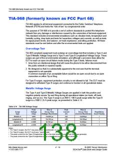
Longitudinal Voltage Surge
The Type A and Type B Longitudinal Voltage Surges are applied in both positive and
negative polarity during all operational states. The Type A surge is a 1500 V, 200 A peak
surge applied to the EUT with Tip and Ring tied together with respect to Ground. The
Type B Longitudinal Voltage Surge is a simultaneous surge in which 1500 V and 37.5 A are
applied concurrently to Tip with respect to Ground and Ring with respect to Ground, as
presented in Table 4.14.
Note: Type B surge requirements guarantee only a minimum level of surge protection. For
long term reliability of terminal equipment, consideration should be given to
complying with Type A surges operationally.
On-hook Impedance Limitations
Another important aspect of TIA-968 is on-hook impedance, which is affected by transient
protection. On-hook impedance is analogous to the leakage current between Tip and Ring,
and Tip, Ring, and Ground conductors during various on-hook conditions. "On-hook
Impedance Measurements" (next paragraph) outlines criteria for on-hook impedance and is
listed as part of the Ringer Equivalent Number (REN). The REN is the largest of the unitless
quotients not greater than five; the rating is specified as the actual quotient followed by the
letter of the ringer classification (for example, 2B).
On-hook Impedance Measurements
On-hook impedance measurements are made between Tip and Ring and between Tip and
Ground and Ring and Ground. For all DC voltages up to and including 100 V, the DC
resistance measured must be greater than 5 Mꢂ. For all DC voltages between 100 V and
200 V, the DC resistance must be greater than 30 kꢂ. The REN values are then determined
by dividing 25 Mꢂ by the minimum measured resistance up to 100 V and by dividing
150 kꢂ by the minimum measured resistance between 100 V and 200 V.
On-hook impedance is also measured during the application of a simulated ringing signal.
This consists of a 40 V rms through 150 V rms ringer signal at frequencies ranging from
15.3 Hz to 68 Hz superimposed on a 56.5 V dc for a class “B” ringer. During this test, the
total DC current may not exceed 3 mA. In addition, the minimum DC resistance measured
between Tip and Ring must be greater than 1600 ꢂ, while the DC resistance measured
between the Tip and Ring conductors and Ground must be greater than 100 kꢂ. The REN
values for the simulated ringing test are determined by dividing the maximum DC current
flowing between Tip and Ring by 0.6 mA, and by dividing 8000 ꢂ by the minimum
impedance value measured.
© 2002 Teccor Electronics
4 - 15
http://www.teccor.com
+1 972-580-7777
®
SIDACtor Data Book and Design Guide

 TECCOR [ TECCOR ELECTRONICS ]