AN1002
Application Notes
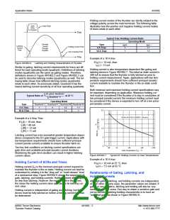
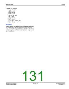
The following table and Figure AN1002.9 show the relationship of
gating, latching, and holding of a 4 A device.
*
Typical 4 A Triac Gating, Latching,
and Holding Relationship
A
K
A
K
Sensitive
SCR
Power
SCR
Quadrants or Operating Mode
Parameter
IGT (mA)
IL (mA)
Quadrant I
10
Quadrant II Quadrant III Quadrant IV
17
48
10
18
12
12
27
13
12
G
12
10
G
IH (mA)
*
MT2
MT1
MT2
Sensitive
Triac
Power
Triac
MT1
G
G
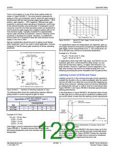
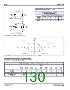
Resistor is provided for limiting gate
*
current (I
) peaks to power device.
GTM
Figure AN1002.8
“Amplified Gate” Thyristor Circuit
(mA)
I (+)
H
20
QUADRANT II
QUADRANT I
I
(Solid Line)
GT
I (Dotted Line)
L
10
(mA)
50
40
30
20
10
0
10
20
30
40
10
20
QUADRANT III
QUADRANT IV
I (–)
H
Figure AN1002.9
Typical Gating, Latching, and Holding Relationships of 4 A Triac at 25 °C
The relationships of gating, latching, and holding for several
device types are shown in the following table. For convenience
all ratios are referenced to Quadrant I gating.
Typical Ratio of Gating, Latching, and Holding Currents at 25 °C
Ratio
I
I
(II)
I
(III)
I
(IV)
I (I)
L
I
(II)
I (III)
L
I (IV)
L
I
(+)
I (-)
H
GT
------------------
GT
--------------------
GT
--------------------
L
H
---------------
---------------
(I)
---------------
---------------
---------------
(I)
---------------
(I)
(I)
I
(I)
I
(I)
I
(I)
I
I
(I)
I
(I)
I
I
GT
1.6
GT
2.5
GT
2.7
GT
GT
GT
GT
GT
GT
Devices
4 A Triac
1.2
4.8
1.2
1.3
1.0
1.2
1.5
1.5
–
1.4
1.8
–
3.1
–
–
1.6
2.4
25
4.0
7.0
–
1.8
2.1
–
2.0
–
–
1.1
2.2
25
1.6
1.9
–
10 A Triac
15 A Alternistor
1 A Sensitive SCR
6 A SCR
–
–
–
3.2
–
–
–
2.6
–
http://www.teccor.com
+1 972-580-7777
AN1002 - 4
©2002 Teccor Electronics
Thyristor Product Catalog

 TECCOR [ TECCOR ELECTRONICS ]