Typical Ratio of ----------------------------------------------------------------------- at 25 °C
(Quadrant 1)
Application Notes
AN1002
Holding current modes of the thyristor are strictly related to the
voltage polarity across the main terminals. The following table
illustrates how the positive and negative holding current modes
of triacs relate to each other.
Gate
Drive
to Thyristor
Gate Pulse
Time
Typical Triac Holding Current Ratio
Operating Mode
Principal
Current
Through
Thyristor
Type
IH(+)
1
IH(-)
1.1
1.3
Latching
Current
Point
Holding Current Point
Zero Crossing Point
4 A Triac
10 A Triac
1
Time
Example of a 10 A triac:
If IH(+) = 10 mA, then
IH(-) = 13 mA
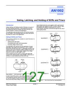
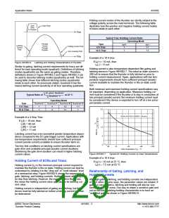
Figure AN1002.6
Latching and Holding Characteristics of Thyristor
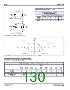
Similar to gating, latching current requirements for triacs are dif-
ferent for each operating mode (quadrant). Definitions of latching
modes (quadrants) are the same as gating modes. Therefore,
definitions shown in Figure AN1002.2 and Figure AN1002.3 can
be used to describe latching modes (quadrants) as well. The fol-
lowing table shows how different latching modes (quadrants)
relate to each other. As previously stated, Quadrant II has the
lowest latching current sensitivity of all four operating quadrants.
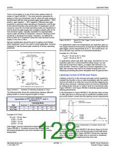
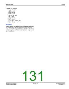
Holding current is also temperature-dependent like gating and
latching shown in Figure AN1002.7. The initial on-state current is
200 mA to ensure that the thyristor is fully latched on prior to
holding current measurement. Again, applications with low tem-
perature requirements should have sufficient principal (anode)
current available to maintain the thyristor in the on-state condi-
tion.
Both minimum and maximum holding current specifications may
be important, depending on application. Maximum holding cur-
rent must be considered if the thyristor is to stay in conduction at
low principal (anode) current; the minimum holding current must
be considered if the device is expected to turn off at a low princi-
pal (anode) current.
I
(In given Quadrant)
L
I
L
Operating Mode
Quadrant II Quadrant III Quadrant IV
Type
Quadrant I
1
4
4
1.2
1.1
1
4 A Triac
10 A Triac
2.0
1
1.1
INITIAL ON-STATE CURRENT = 200 mA dc
1.5
Example of a 4 Amp Triac:
If IL(I) = 10 mA, then
IL(II) = 40 mA
IL(III) = 12 mA
1.0
.5
IL(IV) = 11 mA
Latching current has even somewhat greater temperature depen-
dence compared to the DC gate trigger current. Applications with
low temperature requirements should have sufficient principal
current (anode current) available to ensure thyristor latch-on.
0
Two key test conditions on latching current specifications are
gate drive and available principal (anode) current durations.
Shortening the gate drive duration can result in higher latching
current values.
-40
-15
+25
+65
+100
Case Temperature (TC) – ˚C
Figure AN1002.7
Typical DC Holding Current vs Case Temperatures
Example of a 10 A triac:
Holding Current of SCRs and Triacs
If IH(+) = 10 mA at 25 °C, then
IH(+) ≈ 7.5 mA at 65 °C
Holding current (IH) is the minimum principal current required to
maintain the thyristor in the on state. Holding current can best be
understood by relating it to the “drop-out” or “must release” level
of a mechanical relay. Figure AN1002.6 shows the sequences of
gate, latching, and holding currents. Holding current will always
be less than latching. However, the more sensitive the device,
the closer the holding current value approaches its latching cur-
rent value.
Relationship of Gating, Latching, and
Holding Currents
Although gating, latching, and holding currents are independent
of each other in some ways, the parameter values are related. If
gating is very sensitive, latching and holding will also be very
sensitive and vice versa. One way to obtain a sensitive gate and
not-so-sensitive latching-holding characteristic is to have an
“amplified gate” as shown in Figure AN1002.8.
Holding current is independent of gating and latching, but the
device must be fully latched on before a holding current limit can
be determined.
©2002 Teccor Electronics
Thyristor Product Catalog
AN1002 - 3
http://www.teccor.com
+1 972-580-7777

 TECCOR [ TECCOR ELECTRONICS ]