AN1002
Application Notes
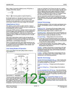
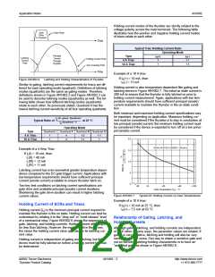
Triacs can be gated on in one of four basic gating modes as
shown in Figure AN1002.3. The most common quadrants for
gating on triacs are Quadrants I and III, where the gate supply is
synchronized with the main terminal supply (gate positive — MT2
positive, gate negative — MT2 negative). Optimum triac gate
sensitivity is achieved when operating in Quadrants I and III due
to the inherent thyristor chip construction. If Quadrants I and III
cannot be used, the next best operating modes are Quadrants II
and III where the gate supply has a negative polarity with an AC
main terminal supply. Typically, Quadrant II is approximately
equal in gate sensitivity to Quadrant I; however, latching current
sensitivity in Quadrant II is lowest. Therefore, it is difficult for
triacs to latch on in Quadrant II when the main terminal current
supply is very low in value.
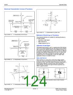
2.0
1.5
1.0
.5
0
-40
-15
+25
+65
+100
Case Temperature (T ) – ˚C
C
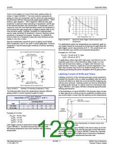
Figure AN1002.4
Typical DC Gate Trigger Current versus Case
Temperature
Special consideration should be given to gating circuit design
when Quadrants I and IV are used in actual application, because
Quadrant IV has the lowest gate sensitivity of all four operating
quadrants.
For applications where low temperatures are expected, gate cur-
rent supply should be increased to at least two to eight times the
°
gate trigger current requirements at 25 C. The actual factor var-
ies by thyristor type and the environmental temperature.
Example of a 10 A triac:
ALL POLARITIES ARE REFERENCED TO MT1
MT2 POSITIVE
If IGT(I) = 10 mA at 25 °C, then
GT(I) = 20 mA at -40 °C
(Positive Half Cycle)
MT2
MT2
+
I
(-)
I
GATE
(+)
In applications where high di/dt, high surge, and fast turn-on are
expected, gate drive current should be steep rising (1 µs rise
time) and at least twice rated IGT or higher with minimum 3 µs
pulse duration. However, if gate drive current magnitude is very
high, then duration may have to be limited to keep from over-
stressing (exceeding the power dissipation limit of) gate junction.
I
GT
GT
GATE
MT1
MT1
REF
MT2
REF
MT2
QII QI
I
-
+ I
GT
GT
QIII QIV
(
-
)
Latching Current of SCRs and Triacs
I
(+)
I
GATE
GT
GT
GATE
Latching current (IL) is the minimum principal current required to
maintain the thyristor in the on state immediately after the switch-
ing from off state to on state has occurred and the triggering sig-
nal has been removed. Latching current can best be understood
by relating to the “pick-up” or “pull-in” level of a mechanical relay.
Figure AN1002.5 and Figure AN1002.6 illustrate typical thyristor
latching phenomenon.
MT1
REF
MT1
REF
-
MT2 NEGATIVE
(Negative Half Cycle)
NOTE: Alternistors will not operate in Q IV
Figure AN1002.3
Definition of Operating Quadrants in Triacs
The following table shows the relationships between different
gating modes in current required to gate on triacs.
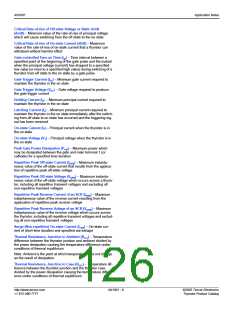
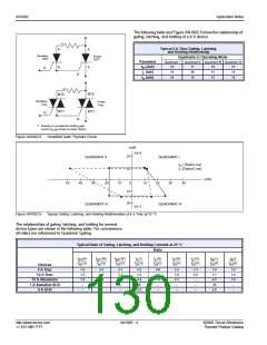
In the illustrations in Figure AN1002.5, the thyristor does not stay
on after gate drive is removed due to insufficient available princi-
pal current (which is lower than the latching current requirement).
I
(In given Quadrant)
GT
Typical Ratio of ---------------------------------------------------------------------------- at 25 °C
I
(Quadrant 1)
GT
Gate Pulse
(Gate Drive to Thyristor)
Operating Mode
Quadrant II Quadrant III Quadrant IV
Type
4 A Triac
10 A Triac
Quadrant I
Time
1
1
1.6
1.5
2.5
1.4
2.7
3.1
Latching
Current
Requirement
Example of 4 A triac:
If IGT(I) = 10 mA, then
Principal
Current
Through
Zero
Crossing Point
Thyristor
I
I
I
GT(II) = 16 mA
GT(III) = 25 mA
GT(IV) = 27 mA
Time
Figure AN1002.5
Latching Characteristic of Thyristor (Device Not
Latched)
Gate trigger current is temperature-dependent as shown in
Figure AN1002.4. Thyristors become less sensitive with
decreasing temperature and more sensitive with increasing
temperature.
In the illustration in Figure AN1002.6 the device stays on for the
remainder of the half cycle until the principal current falls below
the holding current level. Figure AN1002.5 shows the character-
istics of the same device if gate drive is removed or shortened
before latching current requirement has been met.
http://www.teccor.com
+1 972-580-7777
AN1002 - 2
©2002 Teccor Electronics
Thyristor Product Catalog

 TECCOR [ TECCOR ELECTRONICS ]