ICM-20690
4.4 BLOCK DIAGRAM
M2: filter
M2: filter
Accel Digital
Filters (UI)
CV
CV
MUX
MUX
3x Accel
3x Gyro
3x ADC
I2C/SPI
M1: raw
M1: raw
To Host
Select ODR &
FSR
Sensor
Slave
Registers
Interface
Gyro Digital
Filters (UI)
CV
CV
3x ADC
1x ADC
SRAM/FIFO
1 Kbyte
Temp Sensor
Digital Filters
(UI)
Temp
Sensor
M2: filter
1x FSYNC
Input
CV
CV
MUX
M1: raw
OIS FSR & ODR
selection
Select ODR & FSR
SPI Slave mode
for OIS
I2C Master mode for
external sensors
Sensor Registers
SPI Slave
I2C Master Interface
M: OIS Modes
1x OIS Controller
(SPI Master) OR External
Sensors (I2C Slaves)
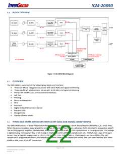
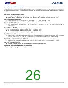
Figure 7. ICM-20690 Block Diagram
4.5 OVERVIEW
The ICM-20690 is comprised of the following key blocks and functions:
Three-axis MEMS rate gyroscope sensor with 16-bit ADCs and signal conditioning
Three-axis MEMS accelerometer sensor with 16-bit ADCs and signal conditioning
Primary I2C and SPI serial communications interfaces
Self-Test
Clocking
Sensor Data Registers
FIFO
Interrupts
Digital-Output Temperature Sensor
Bias and LDOs
Charge Pump
Standard Power Modes
4.6 THREE-AXIS MEMS GYROSCOPE WITH 16-BIT ADCS AND SIGNAL CONDITIONING
The ICM-20690 consists of three independent vibratory MEMS rate gyroscopes, which detect rotation about the X-, Y-, and Z- Axes.
When the gyros are rotated about any of the sense axes, the Coriolis Effect causes a vibration that is detected by a capacitive pickoff.
The resulting signal is amplified, demodulated, and filtered to produce a voltage that is proportional to the angular rate. This voltage
is digitized using individual on-chip 16-bit Analog-to-Digital Converters (ADCs) to sample each axis. The full-scale range of the gyro
sensors may be digitally programmed to ±31.25, ±62.5, ±125, ±250, ±500, ±1000, or ±2000 degrees per second (dps). The ADC
sample rate is programmable from 8,000 samples per second, down to 3.9 samples per second, and user-selectable low-pass filters
enable a wide range of cut-off frequencies.
Page 22 of 76
Document Number: DS-000178
Revision: 1.0

 TDK [ TDK ELECTRONICS ]