Input:
Output:
35-75 V
2.5 V
Current:
Package:
15 A
Eighth-brick
Technical Specification
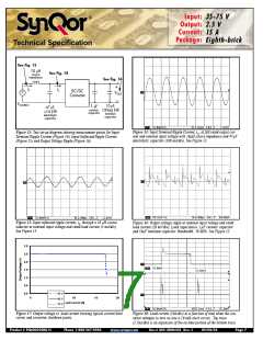
See Fig. 15
10 µH
See Fig. 14
source
impedance
See Fig. 16
iS
iC
DC/DC
Converter
VOUT
VSOURCE
10
µ
Ω
F,
ESR
1 µF
47 µF,
ceramic
100m
<1
Ω ESR
capacitor
tantalum
electrolytic
capacitor
capacitor
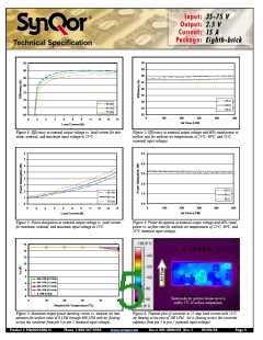
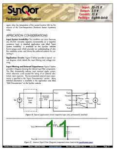
Figure 13: Test set-up diagram showing measurement points for Input
Terminal Ripple Current (Figure 14), Input Reflected Ripple Current
(Figure 15) and Output Voltage Ripple (Figure 16).
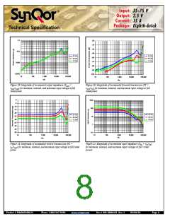
Figure 14: Input Terminal Ripple Current, i , at full rated output cur-
c
rent and nominal input voltage with 10
µH source impedance and 47µF
electrolytic capacitor (100 mA/div). See Figure 13.
Figure 15: Input reflected ripple current, i , through a 10 µH source
inductor at nominal input voltage and rated load current (5 mA/div).
See Figure 13.
Figure 16: Output voltage ripple at nominal input voltage and rated
load current (20 mV/div). Load capacitance: 1 F ceramic capacitor
and 10 F tantalum capacitor. Bandwidth: 20 MHz. See Figure 13.
s
µ
µ
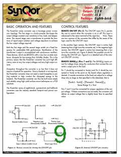
3.0
2.5
2.0
1.5
1.0
0.5
0.0
35 V
48 V
75 V
0
5
10
15
20
Load Current (A)
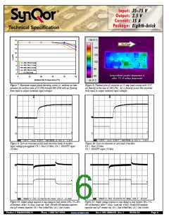
Figure 17: Output voltage vs. load current showing typical current limit
curves and converter shutdown points.
Figure 18: Load current (10A/div) as a function of time when the con-
verter attempts to turn on into a 10 m short circuit. Top trace
(2.5ms/div) is an expansion of the on-time portion of the bottom trace.
Ω
Product # PQ60025EML15
Phone 1-888-567-9596
www.synqor.com
Doc.# 005-2EM625E Rev. C
09/08/05
Page 7

 SYNQOR [ SYNQOR WORLDWIDE HEADQUARTERS ]