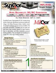
MQFL-28-05S
Output:
Current:
5.0 V
24 A
Technical Specification
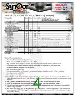
MQFL-28-05S ELECTRICAL CHARACTERISTICS (Continued)
Parameter
Min. Nom. Max. Units Notes & Conditions
Group A
Vin=28V DC 5%, Iout = 24A, CL = 0
µF,
Subgroup13
10
free running unless otherwise specified
ISOLATION CHARACTERISTICS
Isolation Voltage (dielectric strength)
Input RTN to Output RTN
Any Input Pin to Case
500
500
500
100
100
V
V
V
1
1
1
1
1
1
Any Output Pin to Case
Isolation Resistance (input rtn to output rtn)
Isolation Resistance (any pin to case)
Isolation Capacitance (input rtn to output rtn)
FEATURE CHARACTERISTICS
Switching Frequency (free running)
Synchronization Input
M
Ω
M
Ω
nF
44
500
550
600
kHz
1, 2, 3
Frequency Range
500
2
-0.5
20
700
10
0.8
80
kHz
V
V
%
1, 2, 3
1, 2, 3
1, 2, 3
Logic Level High
Logic Level Low
Duty Cycle
See Note 5
Synchronization Output
Pull Down Current
Duty Cycle
20
25
mA
%
VSYNC OUT = 0.8V
Output connected to SYNC IN of another MQFL converter
See Note 5
See Note 5
75
Enable Control (ENA1 and ENA2)
Off-State Voltage
0.8
V
µA
V
µA
V
1, 2, 3
See Note 5
1, 2, 3
Module Off Pulldown Current
On-State Voltage
Module On Pin Leakage Current
Pull-Up Voltage
80
2
Current drain required to ensure module is off
20
4.5
Maximum current draw from pin allowed with module still on See Note 5
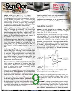
See Figure A 1, 2, 3
3.2
4.0
RELIABILITY CHARACTERISTICS
Calculated MTBF (MIL-STD-217F2)
3
GB @ Tcase=70
ºC
2800
440
TBD
10 Hrs.
3
AIF @ Tcase=70
ºC
10 Hrs.
3
Demonstrated MTBF
10 Hrs.
WEIGHT CHARACTERISTICS
Device Weight
79
g
Electrical Characteristics Notes
1. Converter will undergo input over-voltage shutdown.
2. Derate output power to 50% of rated power at Tcase = 135º C.
3. High or low state of input voltage must persist for about 200 s to be acted on by the lockout or shutdown circuitry.
µ
4. Current limit inception is defined as the point where the output voltage has dropped to 90% of its nominal value.
5. Parameter not tested but guaranteed to the limit specified.
6. Load current transition time ≥ 10
7. Settling time measured from start of transient to the point where the output voltage has returned to 1% of its final value.
8. Line voltage transition time ≥ 100 s.
9. Input voltage rise time ≤ 250 s.
µs.
µ
µ
10. Operating the converter at a synchronization frequency above the free running frequency will cause the converter’s efficiency to be
slightly reduced and it may also cause a slight reduction in the maximum output current/power available. For more information consult
the factory.
11. After a disable or fault event, module is inhibited from restarting for 300ms. See Shut Down section on Page 9.
12. SHARE pin outputs a power failure warning pulse during a fault condition. See Current Share section on Page 11.
13. Only the ES and HB grade products are tested at three temperatures. The B and C grade products are tested at one temperature. Please refer to the
ESS table on Page 13 for details.
14. These derating curves apply for the ES- and HB- grade products. The C- grade product has a maximum case temperature of 100º C and a maximum
junction temperature rise of 20º C above TCASE. The B- grade product has a maximum case temperature of 85º C and a maximum junction tempera-
ture rise of 20º C at full load.
Product # MQFL-28-05S
Phone 1-888-567-9596
www.synqor.com
Doc.# 005-2MQ050S Rev. C
1/21/08
Page 4

 SYNQOR [ SYNQOR WORLDWIDE HEADQUARTERS ]