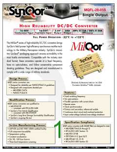
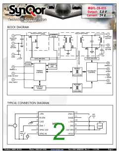
MQFL-28-05S
Output:
Current:
5.0 V
24 A
Technical Specification
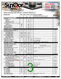
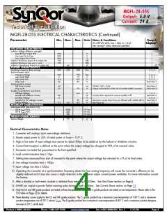
MQFL-28-05S ELECTRICAL CHARACTERISTICS
Parameter
Min. Nom. Max. Units Notes & Conditions
Group A
Vin=28V DC 5%, Iout = 24A, CL = 0
free running unless otherwise specified
µF,
Subgroup13
10
ABSOLUTE MAXIMUM RATINGS
Input Voltage
Non-Operating
60
60
-0.8
-1.2
V
V
V
V
Operating 1
Reverse Bias (TCASE = 125ºC)
Reverse Bias (TCASE = -55ºC)
Isolation Voltage (input/output to case, input to output)
Continuous
-500
-800
-55
500
800
135
135
300
50
V
V
°C
°C
°C
V
Transient (≤100 µs)
Operating Case Temperature 2
Storage Case Temperature
-65
Lead Temperature (20 sec)
Voltage at ENA1, ENA2, SYNC IN
INPUT CHARACTERISTICS
Operating Input Voltage Range (continuous)
Operating Input Voltage Range (transient, 1 sec)
Input Under-Voltage Lockout 3
Turn-On Voltage Threshold
-1.2
16
16
28
28
40
50
V
V
1, 2, 3
4, 5, 6
14.75
13.80
0.50
15.50
14.40
1.10
16.00
15.00
1.80
V
V
V
1, 2, 3
1, 2, 3
1, 2, 3
Turn-Off Voltage Threshold
Lockout Voltage Hysteresis
Input Over-Voltage Shutdown 3
Turn-Off Voltage Threshold
54.0
50.0
2.0
56.8
51.4
5.3
60.0
54.0
8.0
9.5
160
5
V
V
V
A
mA
mA
mA
mA
1, 2, 3
1, 2, 3
1, 2, 3
1, 2, 3
1, 2, 3
1, 2, 3
1, 2, 3
1, 2, 3
Turn-On Voltage Threshold
Shutdown Voltage Hysteresis
Maximum Input Current
Vin = 16V; Iout = 24A
No Load Input Current (operating)
Disabled Input Current (ENA1)
Disabled Input Current (ENA2)
Input Terminal Current Ripple (peak to peak)
OUTPUT CHARACTERISTICS
Output Voltage Set Point (TCASE = 25ºC)
Output Voltage Set Point Over Temperature
Output Voltage Line Regulation
Output Voltage Load Regulation
Total Output Voltage Range
110
2
25
40
Vin = 16V, 28V, 50V
Vin = 16V, 28V, 50V
Bandwidth = 100 kHz – 10 MHz; see Figure 14
50
60
4.95
4.92
-20
15
4.90
5.00
5.00
0
25
5.00
15
5.05
5.08
20
V
V
mV
mV
V
mV
A
W
A
A
A
Vout at sense leads
“
1
2, 3
“
“
“
; Vin = 16V, 28V, 50V
1, 2, 3
1, 2, 3
1, 2, 3
1, 2, 3
1, 2, 3
1, 2, 3
1, 2, 3
1, 2, 3
1, 2, 3
1, 2, 3
See Note 5
35
; Vout @ (Iout=0A) - Vout @ (Iout=24A)
5.10
30
Output Voltage Ripple and Noise Peak to Peak
Operating Output Current Range
Operating Output Power Range
Output DC Current-Limit Inception 4
Short Circuit Output Current
Back-Drive Current Limit while Enabled
Back-Drive Current Limit while Disabled
Maximum Output Capacitance
DYNAMIC CHARACTERISTICS
Output Voltage Deviation Load Transient 6
For a Positive Step Change in Load Current
For a Negative Step Change in Load Current
Settling Time (either case) 7
Bandwidth = 10 MHz; C =11µF
L
0
0
26
26
24
120
33
29
30
7.5
10
34
Vout ≤ 1.2V
50
10,000
mA
µF
-450
-350
350
100
mV
mV
µs
Total Iout step = 12A ↔ 24A, 2.4A ↔ 12A; C =11µF
4, 5, 6
4, 5, 6
4, 5, 6
L
450
200
“
Output Voltage Deviation Line Transient 8
For a Positive Step Change in Line Voltage
For a Negative Step Change in Line Voltage
Settling Time (either case) 7
-500
-500
500
500
500
mV
mV
µs
Vin step = 16V ↔ 50V; C =11µF
4, 5, 6
4, 5, 6
See Note 5
L
“
250
Turn-On Transient
Output Voltage Rise Time
Output Voltage Overshoot
6
0
5.5
3.0
1.5
10
2
8.0
6.0
3.0
ms
%
ms
ms
ms
Vout = 0.5V → 4.5V
4, 5, 6
See Note 5
4, 5, 6
Turn-On Delay, Rising Vin 9 11
Turn-On Delay, Rising ENA1 11
Turn-On Delay, Rising ENA2 11
EFFICIENCY
ENA1, ENA2 = 5V
ENA2 = 5V
ENA1 = 5V
4, 5, 6
4, 5, 6
Iout = 24A (16Vin)
84
87
84
86
83
85
88
90
88
89
87
88
22
24
%
%
1, 2, 3
1, 2, 3
1, 2, 3
1, 2, 3
1, 2, 3
1, 2, 3
1, 2, 3
1, 2, 3
Iout = 12A (16Vin)
Iout = 24A (28Vin)
%
Iout = 12A (28Vin)
%
Iout = 24A (40Vin)
%
Iout = 12A (40Vin)
%
Load Fault Power Dissipation
Short Circuit Power Dissipation
33
34
W
W
Iout at current limit inception point 4
Vout ≤ 1.2V
Product # MQFL-28-05S
Phone 1-888-567-9596
www.synqor.com
Doc.# 005-2MQ050S Rev. C
1/21/08
Page 3

 SYNQOR [ SYNQOR WORLDWIDE HEADQUARTERS ]