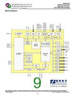
SM59A16U1
8-Bit Micro-controller
64KB with ISP Flash
& 6K+256B RAM embedded
FOSVOS TEL: 021-58998693
11.
Interrupt ........................................................................................................................................................ 75
11.1
Interrupt Enable 0 Register( IEN0 )........................................................................................................ 76
Interrupt Enable 1 Register( IEN1 )........................................................................................................ 76
Interrupt Enable 2 Register( IEN2 )........................................................................................................ 77
Interrupt Request Register( IRCON )..................................................................................................... 77
Interrupt Request Register 2( IRCON2 )................................................................................................ 78
Priority Level Structure.......................................................................................................................... 78
11.2
11.3
11.4
11.5
11.6
12.
13.
Power Management Unit............................................................................................................................... 80
12.1
Idle Mode.............................................................................................................................................. 80
12.2
Stop Mode ............................................................................................................................................ 80
Pulse Width Modulation ( PWM ) ................................................................................................................... 81
13.1
ADC Control Register 2( ADCC2 )......................................................................................................... 83
PWM Time Base Control 0( PWMTBC0 ) .............................................................................................. 84
PWM Time Base Control 1( PWMTBC1 ) .............................................................................................. 85
PWM Output Pair Mode( PWMOPMOD ) .............................................................................................. 85
Time Base Counter by PWM clock( TBCOUNTERL, TBCOUNTERH )................................................... 86
PWM Period( PERIODL, PERIODH ) .................................................................................................... 86
Special Event Compare( SEVTCMPL, SEVTCMPH )............................................................................. 86
PWM Output Enable( PWMEN )............................................................................................................ 86
PWM Special Event( PWMSEV )........................................................................................................... 87
PWM Time Base Post Scale Register( PWMTBPOSTSCALE) .......................................................... 88
PWM Interrupt Flag(PWMINTF ) ....................................................................................................... 88
Dead Time........................................................................................................................................ 89
13.2
13.3
13.4
13.5
13.6
13.7
13.8
13.9
13.10
13.11
13.12
13.12.1
13.12.2
Dead Time 0 for PWM Pair 0( DEADTIME0 ) ............................................................................ 90
Dead Time 1 for PWM Pair 1( DEADTIME1 ) ............................................................................ 90
Dead Time 2 for PWM Pair 2( DEADTIME2 ) ............................................................................ 90
Dead Time 3 for PWM Pair 3( DEADTIME3 ) ............................................................................ 91
Override Disable( OVRIDEDIS ) ............................................................................................... 91
Override Data ( OVRIDEDATA )................................................................................................ 92
PWM Polarity ( PWMPOLARITY )............................................................................................. 93
Fault Configure ( FLTCONFIG ) ........................................................................................................ 94
PWM Fault Inputs ............................................................................................................................. 94
Fault Noise Filter( FLTNF )................................................................................................................ 95
PWM Pair 0 Duty( DUTY0L, DUTY0H )............................................................................................. 95
PWM Pair 1 Duty( DUTY1L, DUTY1H )............................................................................................. 95
PWM Pair 2 Duty( DUTY2L, DUTY2H )............................................................................................. 96
PWM Pair 3 Duty( DUTY3L, DUTY3H )............................................................................................. 96
13.12.3
13.12.4
13.12.5
13.12.6
13.12.7
13.13
13.14
13.15
13.16
13.17
13.18
13.19
14.
15.
IIC function.................................................................................................................................................... 97
14.1
IIC Control Register( IICCTL ) ............................................................................................................... 97
IIC Status Register( IICS )..................................................................................................................... 98
IIC Address1 Register( IICA1 ) .............................................................................................................. 99
IIC Address2 Register( IICA2 ) ............................................................................................................ 101
IIC Read Write Register( IICRWD ) ..................................................................................................... 101
IIC Enable Bus Transaction Register( IICEBT ).................................................................................... 101
14.2
14.3
14.4
14.5
14.6
SPI Function - Serial Peripheral Interface .................................................................................................... 103
15.1
SPI Control Register 1( SPIC1 ).......................................................................................................... 104
SPI Control Register 2( SPIC2 ) ......................................................................................................... 105
SPI Status Register (SPIS )................................................................................................................. 106
SPI Transmit Data Buffer (SPITXD ).................................................................................................... 107
SPI Receive Data Buffer (SPIRXD) ..................................................................................................... 107
15.2
15.3
15.4
15.5
16.
17.
KBI – Keyboard Interface............................................................................................................................. 108
16.1
Keyboard Level Selector Register( KBLS ).......................................................................................... 109
Keyboard Interrupt Enable Register( KBE ) ..........................................................................................110
Keyboard Interrupt Flag Register( KBF )...............................................................................................110
Keyboard De-bounce Control Register( KBD )......................................................................................112
16.2
16.3
16.4
LVI & LVR – Low Voltage Interrupt and Low Voltage Reset ...........................................................................113
Specifications subject to change without notice contact your sales representatives for the most recent information.
ISSFD-M071
SM59A16U1U48VP OB59A16U1U48VP
- 3 -

 SYNCMOS [ SYNCMOS TECHNOLOGIES,INC ]