SM5953
8-Bit Micro-controller
15KB with ISP Flash
& 256B RAM embedded
1
1
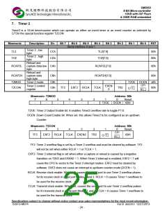
Mode3 If Timer 1 M1 and M0 bits are set to 1, Timer 1
stops. If Timer 0 M1 and M0 bits are set to 1,
Timer 0 acts as two independent 8 bit timers /
counters.
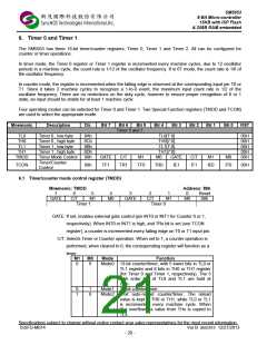
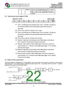
6.2 Timer/counter control register (TCON)
Mnemonic: TCON
Address: 88h
7
6
5
4
3
2
1
0
Reset
TF1
TR1
TF0
TR0
IE1
IT1
IE0
IT0
00h
TF1: Timer 1 overflow flag set by hardware when Timer 1 overflows. This flag can
be cleared by software and is automatically cleared when interrupt is
processed.
TR1: Timer 1 Run control bit. If cleared, Timer 1 stops.
TF0: Timer 0 overflow flag set by hardware when Timer 0 overflows. This flag can
be cleared by software and is automatically cleared when interrupt is
processed.
TR0: Timer 0 Run control bit. If cleared, Timer 0 stops.
IE1: Interrupt 1 edge flag. Set by hardware, when falling edge on external pin
INT1 is observed. Cleared when interrupt is processed.
IT1: Interrupt 1 type control bit. Selects falling edge or low level on input pin to
cause interrupt. IT1=1, interrupt 1 select falling edge trigger. IT1=0, interrupt1
select low level trigger.
IE0: Interrupt 0 edge flag. Set by hardware, when falling edge on external pin
INT0 is observed. Cleared when interrupt is processed.
IT0: Interrupt 0 type control bit. Selects falling edge or low level on input pin to
cause interrupt. IT0=1, interrupt 0 select falling edge trigger. IT0=0, interrupt
0 select low level trigger.
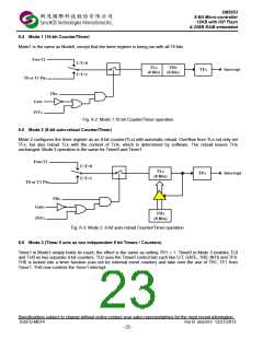
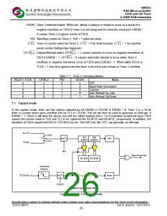
6.3 Mode 0 (13-bit Counter/Timer)
The timer register is configured as a 13-bit register. As the count rolls over from all 1s to all 0s, it sets the timer
interrupt flag TFx. The counted input is enabled to the timer when TRx = 1 and either GATE=0 or INTx = 1. Mode 0
operation is the same for Timer0 and Timer1.
Fig. 6-1: Mode 0 -13 bit Timer / counter operation
Specifications subject to change without notice contact your sales representatives for the most recent information.
ISSFD-M074
Ver B SM5953 12/27/2013
- 21 -

 SYNCMOS [ SYNCMOS TECHNOLOGIES,INC ]