SM5953
8-Bit Micro-controller
15KB with ISP Flash
& 256B RAM embedded
6. Timer 0 and Timer 1
The SM5953 has three 16-bit timer/counter registers: Timer 0, Timer 1 and Timer 2. All can be configured for
counter or timer operations.
In timer mode, the Timer 0 register or Timer 1 register is incremented every machine cycles, due to 12 oscillator
periods in a machine cycle, the count rate is 1/12 of the oscillator frequency. If in 6T mode, the count rate is 1/6 of
the oscillator frequency.
In counter mode, the register is incremented when the falling edge is observed at the corresponding input pin T0 or
T1. Since it takes 2 machine cycles to recognize a 1-to-0 event, the maximum input count rate is 1/2 of the
oscillator frequency. There are no restrictions on the duty cycle, however to ensure proper recognition of 0 or 1
state, an input should be stable for at least 1 machine cycle.
Four operating modes can be selected for Timer 0 and Timer 1. Two Special Function registers (TMOD and TCON)
are used to select the appropriate mode.
Mnemonic
Description
Dir.
Bit 7
Bit 6
Bit 5
Bit 4
Bit 3
Bit 2
Bit 1
Bit 0
RST
Timer 0 and 1
TL0
TH0
TL1
TH1
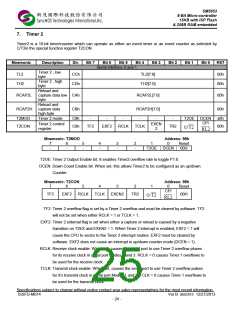
TMOD
Timer 0 , low byte
Timer 0 , high byte
Timer 1 , low byte
Timer 1 , high byte
Timer Mode Control
Timer/Counter
8Ah
8Ch
8Bh
8Dh
89h
TL0[7:0]
00H
00H
00H
00H
00H
TH0[7:0]
TL1[7:0]
TH1[7:0]
GATE
TF1
C/T
M1
M0
GATE
C/T
IT1
M1
IE0
M0
IT0
TCON
88h
TR1
TF0
TR0
IE1
00H
Control
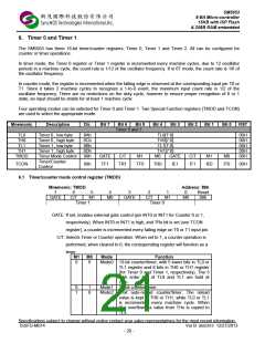
6.1 Timer/counter mode control register (TMOD)
Mnemonic: TMOD
Address: 89h
7
6
C/T
5
M1
4
M0
3
2
C/T
1
M1
0
M0
Reset
00h
GATE
GATE
Timer 1
Timer 0
GATE: If set, enables external gate control (pin INT0 or INT1 for Counter 0 or 1,
respectively). When INT0 or INT1 is high, and TRx bit is set (see TCON
register), a counter is incremented every falling edge on T0 or T1 input pin.
C/T: Selects Timer or Counter operation. When set to 1, a counter operation is
performed, when cleared to 0, the corresponding register will function as a
timer.
M1
M0
Mode
Function
0
0
Mode0 13-bit counter/timer, with 5 lower bits in TL0 or
TL1 register and 8 bits in TH0 or TH1 register
(for Timer 0 and Timer 1, respectively). The 3
high order bits of TL0 and TL1 are hold at
zero.
0
1
1
0
Mode1 16-bit counter/timer.
Mode2 8-bit auto-reload counter/timer. The reload
value is kept in TH0 or TH1, while TL0 or TL1
is incremented every machine cycle. When
TLx overflows, a value from THx is copied to
TLx.
Specifications subject to change without notice contact your sales representatives for the most recent information.
ISSFD-M074 Ver B SM5953 12/27/2013
- 20 -

 SYNCMOS [ SYNCMOS TECHNOLOGIES,INC ]