SM39A16M1
8-Bit Micro-controller
16KB with ISP Flash
& 1K+256B RAM embedded
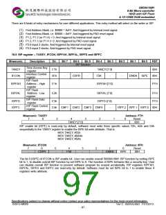
Table 18-1 ISP code area
ISP service program address
No ISP service program
0
1
2
3
4
5
6
7
8
128 bytes ($3F80h ~ $3FFFh)
256 bytes ($3F00h ~ $3FFFh)
384 bytes ($3E80h ~ $3FFFh)
512 bytes ($3E00h ~ $3FFFh)
640 bytes ($3D80h ~ $3FFFh)
768 bytes ($3D00h ~ $3FFFh)
896 bytes ($3C80h ~ $3FFFh)
1.0 K bytes ($3C00h ~ $3FFFh)
ISP service program configurable in N*128 byte (N= 0 ~ 8)
18.3 Program the ISP Service Program
After Lock Bit N is set and ISP service program been programmed, the ISP service program memory will be protected
(locked) automatically. The lock bit N has its own program/erase timing. It is different from the flash memory
program/erase timing so the locked ISP service program can not be erased by flash erase function. If user needs to
erase the locked ISP service program, he can do it by writer only. User can not change ISP service program when
SM39A16M1 was in system.
18.4 Initiate ISP Service Program
To initiate the ISP service program is to load the program counter (PC) with start address of ISP service program and
execute it. There are four ways to do so:
(1) Blank reset. Hardware reset with first flash address blank ($0000=#FFH) will load the PC with start address
of ISP service program. The hardware reset includes MAX810 (power on reset) and external pad reset. The
hardware will issue a strobe window about 256us after hardware reset.
(2) Execute jump instruction can load the start address of the ISP service program to PC.
(3) Enter‟s ISP service program by hardware setting. User can force SM39A16M1 enter ISP service program
by setting P1.2, P1.3 “active low” or P1.4 “ active low” during hardware reset period. The hardware reset
includes MAX810 (power on reset) and external pad reset. The hardware will issue after hardware reset. In
application system design, user should take care of the setting of P1.2,P1.3 or P1.4 at reset period to
prevent SM39A16M1 from entering ISP service program.
(4) Enter‟s ISP service program by hardware setting, the P3.0(RXD) will be detected the two clock signals
during hardware reset period. The hardware reset includes MAX810 (power on reset) and external pad
reset. The hardware will issue to detect 2 clock signals after hardware reset.
During the strobe window, the hardware will detect the status of P1.2, P1.3 (or P1.4)/P1.0. If they meet one of above
conditions, chip will switch to ISP mode automatically. After ISP service program executed, user need to reset the
SM39A16M1, either by hardware reset or by WDT, or jump to the address $0000 to re-start the firmware program.
Specifications subject to change without notice contact your sales representatives for the most recent information.
ISSFD-M069
Ver C SM39A16M1 7/31/2013
- 96 -

 SYNCMOS [ SYNCMOS TECHNOLOGIES,INC ]