SM39A16M1
8-Bit Micro-controller
16KB with ISP Flash
& 1K+256B RAM embedded
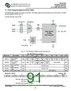
17. 10-bit Analog-to-Digital Converter (ADC)
The SM39A16M1 provides 8 channels 10-bit ADC. The Digital output DATA [9:0] were put into ADCD [9:0]. The ADC
the block diagram show in Fig. 17-1
The ADC interrupt vector is 53H.
VDD
ADCC1[7:0]
ADCCH[2:0]
MUX
Start
AVDD
ADC0
ADCD[9:0]
ADC_ISR
ADC6
ADC7
High Speed
10 Bits
ADC Module
ADC
Fosc
Clock
Divider
AVSS
ADCCS[4:0]
VSS
Fig. 17-1: ADC Analog to Digital converter operation set
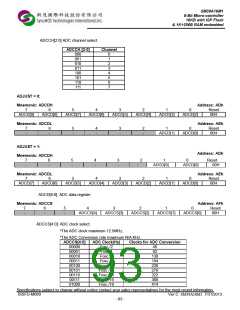
The ADC SFR show as below:
Mnemonic
ADCC1
Description
Dir.
ABh
ACh
ADh
Bit 7
Bit 6
Bit 5
ADC
Bit 4
Bit 3
Bit 2
Bit 1
Bit 0
RST
ADC Control
register 1
ADC7
EN
ADC6
EN
ADC5
EN
PWMT EXTTri
rigger
EN
ADC4
EN
ADC3
EN
ADC2
EN
ADC1
EN
ADC0
EN
00H
08H
00H
ADC Control
register 2
ADJU
ST
ADCM
ODE
ADCC2
Start
ggerE
N
ADCCH[2:0]
ADC data high
byte
ADC data low
byte
ADCDH
ADCDH [7:0]
ADCDL [7:0]
ADCDL
ADCCS
AEh
AFh
00H
00H
ADC clock select
-
-
-
ADCCS[4:0]
1
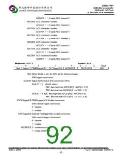
Mnemonic: ADCC1
Address: ABh
7
6
5
4
3
2
0
Reset
ADC7EN
ADC6EN
ADC5EN
ADC4EN
ADC3EN
ADC2EN
ADC1EN
ADC0EN
00H
ADC7EN: ADC channels 7 enable.
ADC7EN = 1 - Enable ADC channel 7
ADC6EN: ADC channels 6 enable.
Specifications subject to change without notice contact your sales representatives for the most recent information.
ISSFD-M069 Ver C SM39A16M1 7/31/2013
- 91 -

 SYNCMOS [ SYNCMOS TECHNOLOGIES,INC ]