HV300
___________________________________________________________________________________________
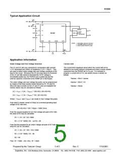
Typical Application Circuit
Long
Pin
GND
8
Jumper
Short
VDD
Pin
GND
PWRGD
1
487K R1
9.09K R2
9.09K R3
ENABLE
3
2
UV
OV
+5V
DC/DC
PWM
CONVERTER
Cload
HV300
COM
RAMP
7
VEE
4
SENSE
GATE
6
5
NOTES: 1. Undervoltage Lockout (UV) set to 35V.
2. Overvoltage Lockout (OV) set to 65V.
3. Remove Jumper if Short Pin is used.
10nF
C1
Long
Pin
-48V
R4
Q1
0.05
IRF530
Application Information
Under Voltage and Over Voltage Detection
Current Limit
The UV and OV pins are connected to comparators with nominal
The current limit magnitude above which the current will not be
allowed to rise during startup is programmed using a sense resistor
connected from the SENSE pin to VEE pin. For example to
program a current limit of 1A, one would choose a resistor as
follows:
1.21V thresholds and 100mV of hysteresis (1.21V ± 50mV). They
are used to detect under voltage and over voltage conditions at the
input to the circuit. Whenever the OV pin rises above its threshold
or the UV pin falls below its threshold the GATE voltage is
immediately pulled low, the PWRGD pin is pulled low and the
external capacitor connected to the RAMP pin is discharged.
Rsense = 50mV / Isense
Rsense = 50mV / 1A
Rsense = 50mΩ
The under voltage and over voltage trip points can be programmed
by means of the three resistor divider formed by R1, R2 and R3.
Since the input currents on the UV and OV pins are negligible the
resistor values may be calculated as follows:
UV = VUVH = 1.26 = VEEUV * (R2+R3) / (R1+R2+R3)
OV = VOVL = 1.16 = VEEOV * R3 / (R1+R2+R3)
Where VEEUV and VEEOV are Under & Over Voltage Set points.
If we select a divider current of 100µA at a nominal operating input
voltage of 50 Volts then
(R1+R2+R3) = 50V / 100µA = 500K Ohms
From the second equation for an Over voltage set point of 65 Volts
the value of R3 may be calculated.
OV = 1.16 = 65 * R3 / 500K
R3 = (1.16 * 500K) / 65; Let R3 = 9K
From the first equation for an Under Voltage set point of 35 Volts the
value R2 can be calculated.
UV = 1.26 = 35 * (R2 + R3) / 500K
R2 = (1.26 * 500K) / 35 – 9K
R2 = 9K
Then R1 = 500K – (R2 +R3); R1 = 482K
Prepared by the Telecom Group
5 of 5
Rev. E
7/19/2001
_________________________________________________________________ ______________________________________________
Supertex, Inc. 1235 Bordeaux Drive, Sunnyvale, CA 94089 TEL: (408) 744-0100 FAX: (408) 222-4895 www.supertex.com

 SUPERTEX [ Supertex, Inc ]