VIPER16
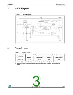
Electrical data
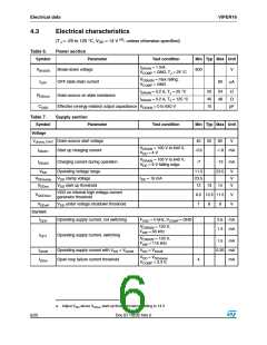
Table 8.
Symbol
Controller section
Parameter
Test condition
Min Typ Max Unit
Error amplifier
VREF_FB
FB reference voltage
3.2 3.3 3.4
V
IFB_PULL UP Current pull up
-1
2
μA
GM
Trans conductance
mA/V
Current setting (LIM) pin
VLIM_LOW Low level clamp voltage
ILIM = -100 μA
0.5
3
V
Compensation (COMP) pin
VCOMPH
VCOMPL
Upper saturation limit
Burst mode threshold
TJ = 25 °C
TJ = 25 °C
TJ = 25 °C
V
V
1
4
1.1 1.2
VCOMPL_HYS Burst mode hysteresis
HCOMP ΔVCOMP / ΔIDRAIN
40
mV
V/A
kΩ
μA
μA
9
RCOMP(DYN) Dynamic resistance
VFB = GND
15
Source / sink current
ICOMP
VFB > 100 mV
150
220
Max source current
VCOMP = GND, VFB = GND
Current limitation
ILIM = -10 μA, VCOMP = 3.3 V,
TJ = 25 °C
IDlim
Drain current limitation
0.38 0.4 0.42
A
tSS
Soft-start time
8.5
450
85
ms
ns
TON_MIN
IDlim_bm
Minimum turn ON time
Burst mode current limitation
VCOMP = VCOMPL
mA
Overload
tOVL
Overload time
50
1
ms
s
tRESTART
Restart time after fault
Oscillator section
FOSC Switching frequency
VIPer16L
VIPer16H
54
60
66 kHz
103 115 127 kHz
F
OSC = 60 kHz
OSC = 115 kHz
4
8
kHz
kHz
Hz
FD
Modulation depth
F
FM
Modulation frequency
Maximum duty cycle
230
DMAX
70
80
%
Thermal shutdown
TSD
Thermal shutdown temperature
Thermal shutdown hysteresis
150 160
30
°C
°C
THYST
Doc ID 15232 Rev 5
7/25

 STMICROELECTRONICS [ ST ]