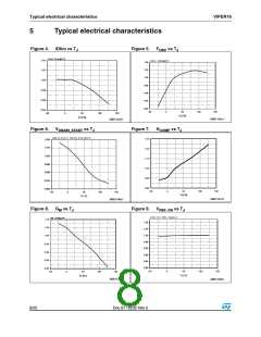
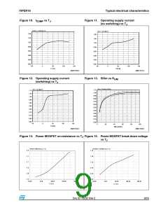
Electrical data
VIPER16
4.3
Electrical characteristics
(a)
(T = -25 to 125 °C, V = 14 V ; unless otherwise specified)
J
DD
Table 6.
Power section
Symbol
VBVDSS
IOFF
Parameter
Test condition
IDRAIN = 1 mA,
Min Typ Max Unit
Break-down voltage
800
V
VCOMP = GND, TJ = 25 °C
V
= max rating,
DRAIN
OFF state drain current
60
μA
VCOMP = GND
DRAIN = 0.2 A, TJ = 25 °C
IDRAIN = 0.2 A, TJ = 125 °C
I
20
40
10
24
48
Ω
Ω
RDS(on)
COSS
Drain-source on state resistance
Effective (energy related) output capacitance VDRAIN = 0 to 640 V
pF
Table 7.
Symbol
Supply section
Parameter
Test condition
Min Typ Max Unit
Voltage
VDRAIN
Drain-source start voltage
Start up charging current
40
50
60
V
_START
V
DRAIN = 100 V to 640 V,
IDDch1
-0.6
-1.8 mA
-13 mA
VDD = 4 V
VDRAIN = 100 V to 640 V,
IDDch2
Charging current during operation
-7
VDD = 9 V falling edge
VDD
VDDclamp
VDDon
Operating voltage range
VDD clamp voltage
11.5
23.5
12
23.5
14
V
V
V
IDD = 15 mA
VDD start up threshold
13
VDD on internal high voltage current
generator threshold
VDDCSon
9.5 10.5 11.5
7
V
V
VDDoff
Current
IDD0
VDD under voltage shutdown threshold
Operating supply current, not switching
Operating supply current, switching
8
9
FOSC = 0 kHz, VCOMP = GND
0.6 mA
1.3 mA
V
= 120 V,
DRAIN
FSW = 60 kHz
IDD1
V
= 120 V,
FSW = 115 kHz
DRAIN
1.5 mA
0.35 mA
mA
IDDoff
IDDol
Operating supply current with VDD < VDDoff
Open loop failure current threshold
VDD < VDDoff
VDD = VDDclamp
VCOMP = 3.3 V,
4
a. Adjust VDD above VDDon start-up threshold before setting to 14 V
Doc ID 15232 Rev 5
6/25

 STMICROELECTRONICS [ ST ]