TS5070 - TS5071
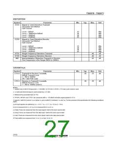
DISTORTION
Symbol
Parameter
Min.
Typ.
Max.
Unit
STDX
Signal to Total Distortion Transmit
Sinusoidal Test Method
Half Channel
Level = 3dBm0
Level = -30dBm0 to 0dBm0
Level = -40dBm0
33
36
30
25
dBp
dBp
dBp
dBp
Level = -45dBm0
STDR
Signal to Total Distortion Receive
Sinusoidal Test Method
Half Channel
Level = 3dBm0
Level = -30dBm0 to 0dBm0
Level = -40dBm0
Level = -45dBm0
33
36
30
25
dBp
dBp
dBp
dBp
SFDX
SFDR
IMD
Single Frequency Distortion Transmit
Single Frequency Distortion Receive
-46
-46
-41
dB
dB
dB
Intermodulation Distortion Transmit or Receive
Two Frequencies in the Range 300Hz to 3400Hz
CROSSTALK
Symbol
Parameter
Min.
Typ.
Max.
-75
Unit
CTX-R Transmit to Receive Crosstalk,
0dBm0 Transmit Level
-90
dB
f = 300 to 3400Hz
DR = Idle PCM Code
CTR-X Receive to Transmit Crosstalk,
0dBm0 Receive Level
-90
-70
dB
f = 300 to 3400Hz (note 4)
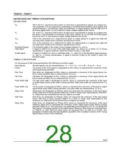
Notes:
1. Applies only to MCLK frequencies 1.536 MHz. At 512 kHz A 50:50 2 % duty cycle must be used.
≥
±
2. A multi-tone test technique is used (peak/rms 9.5 dB).
≤
3. Measured by grounded input at VFXI.
4. PPSRX, NPSRX and CTR-X are measured with a – 50 dBm0 activation signal applied to VFXI.
A signal is Valid if it is above VIH or below VIL and invalidif it is between VIL and VIH. For the purpose of the specification the following conditions
apply :
a) All input signals are defined as VIL = 0.4 V, VIH = 2.7 V, tR < 10 ns, tF 10 ns
b) tR is measured from VIL to VIH, tF is measured from VIH to VIL
c) Delay Times are measured from the input signal Valid to the clock input invalid
d) Setup Times are measured from the data input Validto the clock input invalid
e) Hold Times are measured from the clock signal Valid to the data input invalid
f) Pulse widths are measured from VIL to VIL or from VIH to VIH
27/32

 STMICROELECTRONICS [ ST ]