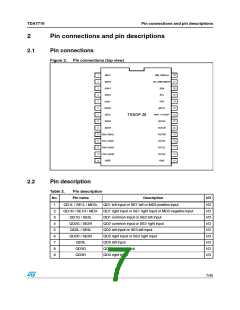
Pin connections and pin descriptions
TDA7719
I/O
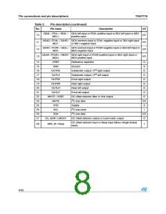
Table 2.
No.
Pin description (continued)
Pin name
Description
QD4L / FD4+ / SE4L / QD4 left input or FD4L positive input or SE4 left input or MD1
MD1+ positive input
10
11
12
13
I/O
I/O
I/O
I/O
QD4G / FD4L- / SE4R / QD4 common input or FD4L negative input or SE4 right input
MD1- or MD1 negative input
QD4G / FD4R- / SE5L / QD4 common input or FD4R negative input or SE5 left input or
MD2- MD2 negative input
QD4R / FD4R+ / SE5R / QD4 right input or FD4R positive input or SE5 right input or
MD2+
MD2 positive input
14
15
16
17
18
19
20
21
22
23
24
25
26
27
CREF
Reference capacitor
O
S
GND
Ground
OUTR2
OUTL2
Subwoofer output / 2nd right output
Subwoofer output / 2nd left output
Front right output
O
O
O
O
O
O
O
I/O
S
OUTRF
OUTRR
OUTLR
OUTLF
Rear right output
Rear left output
Front left output
WinTC / VREF
MUTE
DC offset detector filter or Vref output
I2C bus data
VDD
Supply
SCL
I2C bus clock
I
SDA
I2C bus data
I/O
O
DC_ERR / LMOUT
DC offset detector output or Level meter output
DC offset detector input or Beep input (Mono Single-Ended
input)
28
WIN_IN / Beep
I
8/45

 STMICROELECTRONICS [ ST ]