Description
TDA7719
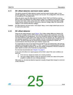
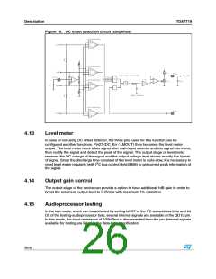
Figure 19. DC offset detection circuit (simplified)
4.13
Level meter
In case of not using DC offset detector, the three pins used for this function can be
configured as other functions. Pin27 (DC_Err / LMOUT) then becomes the level meter
output. The level meter block takes signal after main input selector and mix signal into mono,
then rectify the signal and detect the peak of the signal. The output stage of level meter
removes the DC voltage of the signal and the output voltage level shows exactly the Vpeak
of signal. Since the discharge time constant of the level meter is quite slow, it is necessary to
2
reset level meter regularly (with I C bus control Byte3 Bit6) to get correct peak information of
the signal.
4.14
4.15
Output gain control
The output stage of the device can provide a option to have additional 1dB gain in order to
boost the maximum output level to 2.2Vrms with maximum 1% distortion.
Audioprocessor testing
2
In the test mode, which can be activated by setting bit D7 of the I C subaddress byte and bit
D0 of the testing-audioprocessor byte, several internal signals are available at the QD1L pin.
In this mode, the input resistance of 100kOhm is disconnected from the pin. Internal signals
available for testing are listed in the data-byte specification.
26/45

 STMICROELECTRONICS [ ST ]