TDA7498L
Applications information
5.5
Internal and external clocks
The clock of the class-D amplifier can be generated internally or can be driven by an
external source.
If two or more class-D amplifiers are used in the same system, it is recommended that all
devices operate at the same clock frequency. This can be implemented by using one
TDA7498L as master clock, while the other devices are in slave mode, that is, externally
clocked. The clock interconnect is via pin SYNCLK of each device. As explained below,
SYNCLK is an output in master mode and an input in slave mode.
5.5.1
Master mode (internal clock)
Using the internal oscillator, the output switching frequency, f , is controlled by the
SW
resistor, R
, connected to pin ROSC:
OSC
6
f
= 10 / ((R
* 16 + 182) * 4) kHz
SW
OSC
where R
is in kΩ.
OSC
In master mode, pin SYNCLK is used as a clock output pin whose frequency is:
f
= 2 * f
SYNCLK
SW
For master mode to operate correctly then resistor R
below in Table 9.
must be less than 60 kΩ as given
OSC
5.5.2
Slave mode (external clock)
In order to accept an external clock input the pin ROSC must be left open, that is, floating.
This forces pin SYNCLK to be internally configured as an input as given in Table 9.
The output switching frequency of the slave devices is:
f
= f
/ 2
SW
SYNCLK
Table 9.
How to set up SYNCLK
Mode
ROSC
SYNCLK
Master
Slave
R
OSC < 60 kΩ
Output
Input
Floating (not connected)
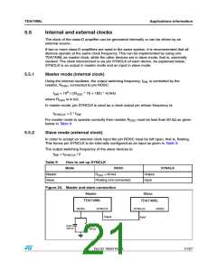
Figure 24. Master and slave connection
Master
Slave
TDA7498L
TDA7498L
ROSC
SYNCLK
SYNCLK
ROSC
Output
Input
Cosc
100 nF
Rosc
39 kΩ
Doc ID 16504 Rev 3
21/27

 STMICROELECTRONICS [ ST ]