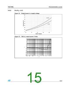
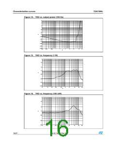
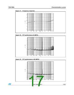
TDA7498L
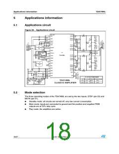
Applications information
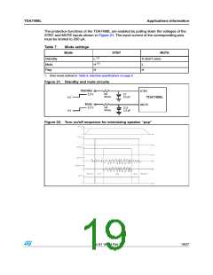
The protection functions of the TDA7498L are enabled by pulling down the voltages of the
STBY and MUTE inputs shown in Figure 21. The input current of the corresponding pins
must be limited to 200 µA.
Table 7.
Mode settings
Mode
STBY
MUTE
X (don’t care)
Standby
Mute
L (1)
H (1)
H
L
Play
H
1. Drive levels defined in Table 6: Electrical specifications on page 9
Figure 21. Standby and mute circuits
Standby
STBY
R2
30 kΩ
3.3 V
C7
2.2 µF
0 V
0 V
TDA7498L
Mute
3.3 V
MUTE
R4
30 kΩ
C15
2.2 µF
Figure 22. Turn on/off sequence for minimizing speaker “pop”
Doc ID 16504 Rev 3
19/27

 STMICROELECTRONICS [ ST ]