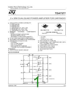
TDA7377
High Application Flexibility
The fully complementary output stage was made
possible by the development of a new compo-
nent: the ST exclusivepower ICV PNP.
The availability of 4 independent channels makes
it possible to accomplish several kinds of applica-
tions ranging from 4 speakers stereo (F/R) to 2
speakers bridge solutions.
In case of working in single ended conditions the
polarity of the speakers driven by the inverting
amplifier must be reversed respect to those driven
by non inverting channels.
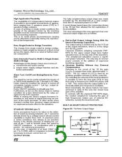
A novel design based upon the connection shown
in fig. 20 has then allowed the full exploitation of
its possibilities.
The clear advantagesthis new approachhas over
classical output stagesare as follows:
This is to avoid phase inconveniences causing
sound alterations especially during the reproduc-
tion of low frequencies.
Rail-to-Rail Output Voltage Swing With No
Need of Bootstrap Capacitors.
The output swing is limited only by the VCEsat
of the output transistors, which is in the range
of 0.3Ω (Rsat) each.
Classical solutions adopting composite PNP-
NPN for the upper output stage have higher
saturation loss on the top side of the waveform.
This unbalanced saturation causes a signifi-
cant power reduction. The only way to recover
power consists of the addition of expensive
bootstrapcapacitors.
Easy Single Ended to Bridge Transition
The change from single ended to bridge configu-
rations is made simply by means of a short circuit
across the inputs, that is no need of further exter-
nal components.
Gain Internally Fixed to 20dB in Single Ended,
26dB inBridge
Advantages of this design choice are in terms of:
componentsand space saving
Absolute Stability Without Any External
Compensation.
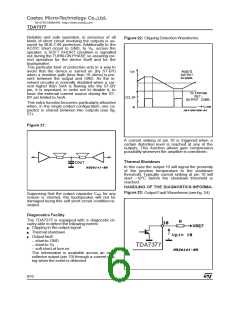
Referring to the circuit of fig. 20 the gain
output noise, supply voltage rejection and dis-
tortion optimization.
VOut/VIn is greater than unity, approximately 1+
R2/R1. The DC output (VCC/2) is fixed by an
auxiliary amplifier common to all the channels.
By controlling the amountof this local feedbackit
is possible to force the loop gain (A*β) to less
than unity at frequency for which the phase shift
is 180°. This means that the output buffer is in-
trinsically stableand notproneto oscillation.
Most remarkably, the above feature has been
achieved in spite of the very low closed loop
gain of the amplifier.
In contrast, with the classical PNP-NPN stage,
the solution adopted for reducing the gain at
high frequencies makes use of external RC
networks,namely the Boucherotcells.
Silent Turn On/Off and Muting/Stand-by Func-
tion
The stand-by can be easily activated by means of
a CMOS level applied to pin 7 through a RC filter.
Under stand-by condition the device is turned off
completely (supply current = 1µA typ.; output at-
tenuation= 80dB min.).
Every ON/OFF operationis virtually pop free.
Furthemore, at turn-on the device stays in muting
condition for a time determined by the value as-
signed to the SVR capacitor.
While in muting the device outputs becomes in-
sensitive to any kinds of signal that may be pre-
sent at the input terminals. In other words every
transient coming from previous stages produces
no unplesantacoustic effectto the speakers.
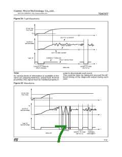
BUILT–IN SHORT CIRCUIT PROTECTION
Figure 20:
TheNew Output Stage
STAND-BY DRIVING (pin 7)
Some precautions have to be taken in the defini-
tion of stand-by driving networks: pin 7 cannot be
directly driven by a voltage source whose current
capability is higher than 5mA. In practical cases
a series resistance has always to be inserted,
having it the double purpose of limiting the cur-
rent at pin 7 and to smooth down the stand-by
ON/OFF transitions - in combination with a ca-
pacitor - for output pop prevention.
In any case, a capacitor of at least 100nF from
pin 7 to S-GND, with no resistance in between, is
necessary to ensure correct turn-on.
OUTPUT STAGE
5/10

 STMICROELECTRONICS [ ST ]