TDA7265
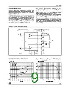
BRIDGE APPLICATION
The detected characteristics of T.H.D. vs Pout
and Frequency Response are shown in fig.19 and
fig.20.
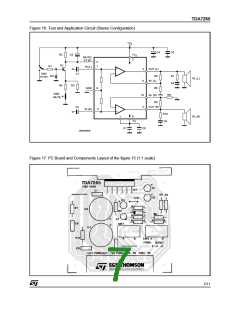
Another application suggestion concerns the
BRIDGE configuration, where the two power am-
plifiers are connected as shown by the schematic
diagram of figure. 18.
This application shows, however, some operative
limits due to dissipation and current capability of
the output stage. For this reason, we reccomend
to use the TDA7265 in bridge with the supply volt-
Ω
With R1=8 , Vs=+/-16V the maximum output
power obtainable is 50W at T.D.H.=10%.
The quiescent current remains unchanged with
respect to the stereo configuration (~80mA as
typical at Vs=+/-16V).
The last point to take into consideration concerns
the short-circuit protection. As for the stereo appli-
cation, the TDA7265 is fully protected against any
kind of short-circuit ( between Out/Gnd, Out/+Vs
and Out/-Vs).
±
Ω
age equal/lower than 16V when the load is 8 ;
Ω
with higher loads (i.e.16 ), the amplifier can work
correctly in the whole supply voltage range.
Figure 18: Bridge Application Circuit
ST-BY/
MUTE
+VS
C3
C4
0.1µF
1000µF
5
3
C1
C7
0.1µF
R5 4.7Ω
7
IN
+
-
4
8
1µF
R1
36KΩ
R2
560Ω
RL
9
R4
560Ω
C8
5.6nF
10
2
R3
36KΩ
C2
-
11
+
1µF
1
6
R6
4.7Ω
-VS
C6
C5
0.1µF
C9
0.1µF
D94AU190
1000µF
Figure 19: Distortion vs. Output Power
Figure 20: Frequency Response of the Bridge Ap-
plications
9/11

 STMICROELECTRONICS [ ST ]