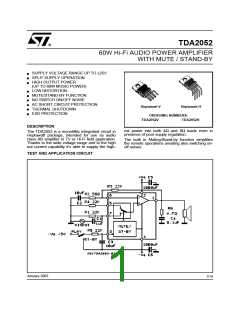
TDA2052
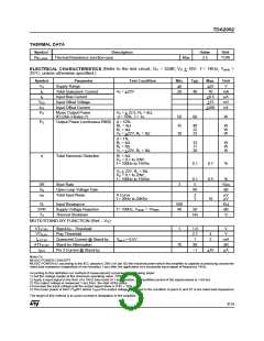
THERMAL DATA
Symbol
Description
Value
Unit
Rth j-case
Thermal Resistance Junction-case
Max
2.5
°C/W
ELECTRICAL CHARACTERISTICS (Refer to the test circuit, GV = 32dB; VS + 18V; f = 1KHz; Tamb
=
°
25 C, unless otherwise specified.)
Symbol
VS
Parameter
Supply Range
Test Condition
Min.
Typ.
Max.
Unit
V
+6
20
+25
70
Iq
Total Quiescent Current
Input Bias Current
VS = +22V
40
mA
µA
mV
nA
Ib
+0.5
+15
+200
VOS
IOS
Input Offset Voltage
Input Offset Current
PO
Music Output Power
IEC268-3 Rules (*)
VS = + 22.5, RL = 4Ω,
d = 10%, t = 1s
50
60
W
PO
Output Power (continuous RMS) d = 10%
RL = 4Ω
RL = 8Ω
VS = +22V, RL = 8Ω
35
30
40
22
33
W
W
W
d = 1%
RL = 4Ω
RL = 8Ω
VS = +22V, RL = 8Ω
32
17
28
W
W
W
d
Total Harmonic Distortion
RL = 4Ω
PO = 0.1 to 20W;
f = 100Hz to 15KHz
0.1
0.7
0.5
%
VS + 22V, RL = 8Ω
PO = 0.1 to 20W;
f = 100Hz to 15KHz
0.1
5
%
V/µs
dB
SR
GV
eN
Slew Rate
3
Open Loop Voltage Gain
Total Input Noise
80
A Curve
f = 20Hz to 20KHz
2
3
µV
µV
10
Ri
SVR
TS
Input Resistance
500
40
KΩ
dB
°C
Supply Voltage Rejection
Thermal Shutdown
f = 100Hz, Vripple = 1VRMS
50
145
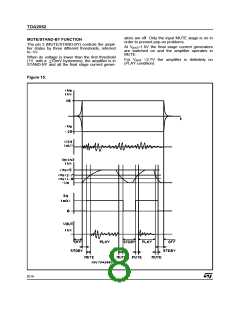
MUTE/STAND-BY FUNCTION (Ref. –VS)
VTST-BY
VTPLAY
Iq ST-BY
ATTST-BY
Ipin3
Stand-by - Threshold
Play Threshold
1
1.8
2.7
1
V
V
4
3
Quiescent Current @ Stand-by
Stand-by Attenuation
Pin 3 Current @ Stand-by
Vpin 3 = 0.5V
mA
dB
µA
70
90
–1
+10
Note (*):
MUSIC POWER CONCEPT
MUSIC POWER is ( according to the IEC clauses n.268-3 of Jan 83) the maximal power which the amplifier is capable of producing across the
rated load resistance (regardless of non linearity) 1 sec after the application of a sinusoidal input signal of frequency 1KHz.
According to this definition our method of measurement comprises the following steps:
1) Set the voltage supply at the maximum operating value -10%
2) Apply a input signal in the form of a 1KHz tone burst of 1 sec duration; the repetition period of the signal pulses is > 60 sec
3) The output voltage is measured 1 sec from the start of the pulse
4) Increase the input voltage until the output signal show a THD = 10%
5) The music power is then V2out/R1, where Vout is the output voltage measured in the condition of point 4) and R1 is the rated load impedance
The target of this method is to avoid excessive dissipation in the amplifier.
3/14

 STMICROELECTRONICS [ ST ]