TDA2052
SHORT-CIRCUIT PROTECTION
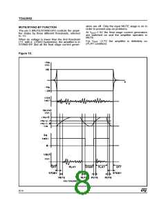
THERMAL PROTECTION
The TDA 2052 has an original circuit which pro-
tects the device during accidental short-circuit be-
tween output and GND / -Vs / +Vs, taking it in
STAND-BY mode, so limiting also dangerous DC
current flowing throught the loudspeaker.
The thermal protection operates on the 125µA
current generator, linearly decreasing its value
from 90°C on. By doing this, the A voltage slowly
decreases thus switching the amplifier first to
MUTE (at 145°C) and then to STAND-BY
°
(155 C).
If a short-circuit or an overload dangerous for the
final transistors are detected, the concerned SOA
circuit sends out a signal to the latching circuit
µ
Thermal Protection Block Diagram
(with a 10 s delay time that prevents fast random
Figure 16:
spikes from inadvertently shutting the amplifier
off) which makes Q1 and Q2 saturate (see Block
Diagram). Q1 immediately short-circuits to ground
the A point turning the final stage off while Q2
short-circuits to ground the external capacitor
driving the pin 3 (Mute/Stand-by) towards zero
potential.
Only when the pin 3 voltage becomes lower than
1V, the latching circuit is allowed to reset itself
and restart the amplifier, provided that the short-
circuit condition has been removed. In fact, a win-
dow comparator is present at the output and it is
aimed at preventing the amplifier from restarting if
the output voltage is lower than 0.35 Total Supply
Voltage or higher than 0.65 Total Supply Voltage.
If the output voltage lies between these two
thresholds, one may reasonably suppose the
short-circuit has been removed and the amplifier
may start operating again.
The maximum allowable power dissipation de-
pends on the size of the external heatsink (ther-
mal resistance case-ambient); figure 17 shows
the dissipable power as a function of ambient
temperature for different thermal resistance.
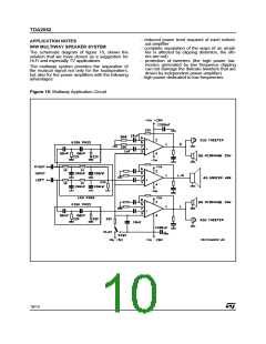
The PLAY/MUTE/STAND-BY function pin (pin 3)
is both ground- and positive supply-compatible
and can be interfaced by means of the R5, C3 net
µ
either to a TTL or CMOS output ( -Processor) or
to a specific application circuit.
The R5, C3 net is fundamental, because connect-
ing this pin directly to a low output impedance
driver such as TTL gate would prevent the correct
operation during a short-circuit. Actually a final
stage overload turns on the protection latching
circuit that makes Q2 try to drive the pin 3 voltage
under 0.8 V. Since the maximum current this pin
can stand is 3 mA, one must make sure the fol-
lowing condition is met:
Figure 17: Maximum Allowable Power Dissipa-
tion vs. Ambient Temperature.
(
−
3mA
)
VA 0.7V
≥
R5
Ω
that yields: R5, min = 1.5 K with VA=5V.
In order to prevent pop-on and -off transients, it is
advisable to calculate the C3, R5 net in such a
way that the STAND-BY/MUTE and MUTE/PLAY
threshold crossing slope (positive at the turn-on
and vice-versa) is less than 100 V/sec.
9/14

 STMICROELECTRONICS [ ST ]