Detailed Features
2.1.1 IR filter
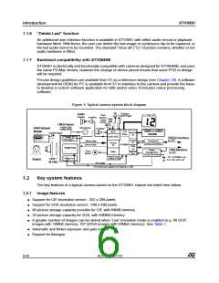
STV0681
For IR filter design, the best choice filter follows the GS0034 dielectric stack filter specification
available from STMicroelectronics. An alternative, although not optimal filter, would be Schott
S8612 doped glass also sold as CM500.
2.2
User interface
The user interface supported by STV0681 comprises of user controls, buzzer sounds or customized
sounds and visual displays.
2.2.1 Push buttons
The following are the functions which are supported by the chipset. These functions are achievable
with no more than 2 push buttons.
1
Mode button (wake-up/switch between modes)
This button allows the user (1.1) to wake the camera up from standby mode when the camera
is to be used for taking pictures, or (1.2) to switch between modes of operation shown in
Chapter 3.
2
Shutter button (shutter/confirm action)
This button allows the user to take a picture or confirm an action, as shown in Chapter 3
The modes of operation are described in Chapter 3.
It may also be desirable to include an on-off slider switch. The advantages and disadvantages as
well as its exact function are discussed in the reference design available from STMicroelectronics.
When a flashgun module is included in the camera, it is necessary to include a flash on/flash off
push button or slider switch depending on the exact flashgun module design. Possible
implementations are discussed in a separate application note AN1312 available from
STMicroelectronics.
2.2.2 LED indicator
The LED indicator displays the camera status when not in Standby/PC suspend mode.
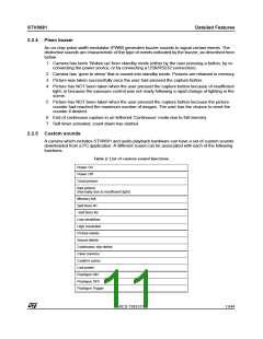
2.2.3 Picture counter using 2 x 7 segment display
STV0681 stores a picture counter value indicating how many images can still be captured.
STV0681 supports a 2x7 segment LCD panel. In ‘Snapshot’ mode and continuous capture mode,
this LCD panel displays the number of pictures still available. This is useful to identify when the user
is approaching the maximum number of images which can be stored (see Table 1). The user can
clear the images stored in memory and continue taking pictures. In other modes, this LCD panel
displays a 2-character code that helps the user to navigate around the modes.
Note: A CIF camera with STV0681 and 64Mbit SDRAM can store up to 320 images by using QCIF mode.
When more than 99 images are still available, the LCD display remains at 99. When the number of
available images is inferior to 99, the LCD display shows how many images are available like in all
other modes.
For suitable numeric LCD panel types, see Section 4.7.
10/44
ADCS 7283313C

 STMICROELECTRONICS [ ST ]