Detailed Features
STV0681
2.6
Anti-flicker exposure and gain control
2.6.1 General
The chipset operates automatic exposure and gain control for either 50Hz or 60Hz mains-driven
indoor lighting, using the same 12MHz crystal. This improves picture quality by selecting a set of
exposure values which minimize ‘flicker’ effects. Detection of the mains frequency is dependant on
the status of the GPIO3 pin, which can be achieved by population of a PCB link at a late stage in
production, once the country of destination is known, without the need to change the crystal
frequency.
The auto exposure and gain algorithm is always enabled during Snapshot’/self-timer/continuous
mode. When the shutter button is pressed in ‘Snapshot’ mode, the chipset captures an image if the
exposure and gain values are suitable for the current scene. If the light has suddenly changed, the
camera may emit an audible tone to indicate that more time is required to reach the correct
exposure target. In ‘Snapshot’ mode the chipset only captures the image data if sufficient light is
present in the image. In continuous capture mode, the chipset captures images regardless of
whether enough light is present.
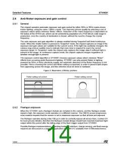
The exposure control algorithm in STV0681 chooses exposure values which minimize “flicker”
effects from occurring under fluorescent lighting. STV0681 can only prevent flicker in lighting
powered by 50Hz or 60Hz electricity supply, but automatic detection of the flicker frequency is not
possible. Hence choosing the correct anti-flicker setting is important, in order to prevent dark stripes
from appearing across the image, and this selection must be done in hardware.
Figure 2: Illustration of flicker problem
Flicker setting not correct
Flicker setting correct
2.6.2 Flashgun exposure
When the STV0681 and a flashgun module are included in the camera, and the flashgun enable
signal is high, the exposure mode operates in a different manner. The CMOS sensor progressive
scan readout requires that the sensor is set to maximum exposure so that all lines are exposed.
The flashgun operates during a few 100 µs in order to correctly expose all sensor lines, (contact ST
for more precise details), therefore the flashgun module design should have reached maximum light
output within this period after the falling edge of the flash trigger output from STV0681.
Possible flashgun implementations, regarding hardware interface, charge sensing, and flash energy
required are discussed in a separate application note AN1312 available from STMicroelectronics.
14/44
ADCS 7283313C

 STMICROELECTRONICS [ ST ]