Electrical characteristics
STM32F405xx, STM32F407xx
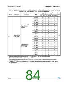
Table 23. Typical and maximum current consumptions in Stop mode
Typ
Max
Symbol
Parameter
Conditions
Unit
TA =
TA =
TA =
TA =
25 °C 25 °C 85 °C 105 °C
Flash in Stop mode, low-speed and high-
speed internal RC oscillators and high-speed
oscillator OFF (no independent watchdog)
Supply
0.45
0.40
0.31
0.28
1.5
1.5
1.1
1.1
11.00 20.00
11.00 20.00
current in
Stop mode
with main
regulator in
Run mode
Flash in Deep power down mode, low-speed
and high-speed internal RC oscillators and
high-speed oscillator OFF (no independent
watchdog)
IDD_STOP
mA
Flash in Stop mode, low-speed and high-
speed internal RC oscillators and high-speed
oscillator OFF (no independent watchdog)
Supply
8.00
8.00
15.00
15.00
current in
Stop mode
with main
regulator in
Low Power
mode
Flash in Deep power down mode, low-speed
and high-speed internal RC oscillators and
high-speed oscillator OFF (no independent
watchdog)
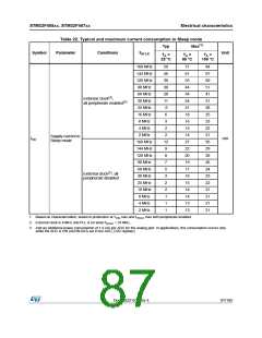
Table 24. Typical and maximum current consumptions in Standby mode
Typ
Max(1)
TA =
85 °C
TA =
105 °C
TA = 25 °C
Symbol
Parameter
Conditions
Unit
VDD
1.8 V
=
VDD
2.4 V
=
VDD =
3.3 V
VDD = 3.6 V
Backup SRAM ON, low-
speed oscillator and RTC ON
3.0
3.4
4.0
20
36
32
Backup SRAM OFF, low-
speed oscillator and RTC ON
2.4
2.4
1.7
2.7
2.6
1.9
3.3
3.0
2.2
16
12.5
9.8
Supply current
IDD_STBY in Standby
mode
µA
Backup SRAM ON, RTC
OFF
24.8
19.2
Backup SRAM OFF, RTC
OFF
1. Based on characterization, not tested in production.
88/185
DocID022152 Rev 4

 STMICROELECTRONICS [ ST ]