STM32F302xx/STM32F303xx
Electrical characteristics
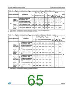
Table 30. Typical and maximum V consumption in Stop and Standby modes
DD
Typ @VDD (VDD=VDDA
)
Max(1)
Symbol Parameter
Conditions
Unit
TA = TA = TA =
25 °C 85 °C 105 °C
2.0 V 2.4 V 2.7 V 3.0 V 3.3 V 3.6 V
Regulator in run mode,
all oscillators OFF
20.05 20.33 20.42 20.50 20.67 20.80 44.2(2) 553 1202(2)
7.63 7.77 7.90 8.07 8.17 8.33 30.6(2) 529 1156(2)
Supply
current in
Stop mode
Regulator in low-power
mode, all oscillators OFF
IDD
µA
Supply
current in
Standby
mode
LSI ON and IWDG ON
0.80 0.96 1.09 1.23 1.37 1.51
-
-
-
LSI OFF and IWDG OFF 0.60 0.74 0.83 0.93 1.02 1.11 5.0(2) 7.8 13.3(2)
1. Data based on characterization results, not tested in production unless otherwise specified.
2. Data based on characterization results and tested in production.
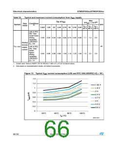
Table 31. Typical and maximum V
consumption in Stop and Standby modes
DDA
Typ @VDD (VDD = VDDA
)
Max(1)
Symbol Parameter
Conditions
Unit
TA = TA = TA =
25 °C 85 °C 105 °C
2.0 V 2.4 V 2.7 V 3.0 V 3.3 V 3.6 V
Regulator in run mode,
all oscillators OFF
1.81 1.95 2.07 2.20 2.35 2.52 3.7
1.81 1.95 2.07 2.20 2.35 2.52 3.7
5.5
5.5
8.8
8.8
Supply
current in
Stop mode
Regulator in low-power
mode, all oscillators
OFF
Supply
LSI ON and IWDG ON 2.22 2.42 2.59 2.78 3.0 3.24
-
-
-
current in
Standby
mode
LSI OFF and IWDG
OFF
1.69 1.82 1.94 2.08 2.23 2.40 3.5
5.4
9.2
IDDA
µA
Regulator in run mode,
all oscillators OFF
1.05 1.08 1.10 1.15 1.22 1.29
1.05 1.08 1.10 1.15 1.22 1.29
-
-
-
-
-
-
Supply
current in
Stop mode
Regulator in low-power
mode, all oscillators
OFF
Supply
current in
Standby
mode
LSI ON and IWDG ON 1.44 1.52 1.60 1.71 1.84 1.98
-
-
-
-
-
-
LSI OFF and IWDG
0.93 0.95 0.98 1.02 1.08 1.15
OFF
1. Data based on characterization results, not tested in production.
Doc ID 023353 Rev 5
65/133

 STMICROELECTRONICS [ ST ]