STA8088EXG
Pin description
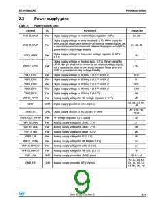
2.3
Power supply pins
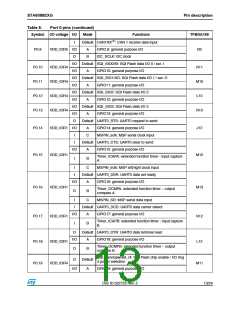
Table 3.
Power supply pins
Symbol
VDD18_MVR
I/O
Functions
TFBGA169
Pwr
Digital supply voltage for main voltage regulator (1.8 V)
D3, G8
Digital supply voltage for core circuitry (1.2 V). When using the
MVR, this pin shall not be driven by an external voltage supply, but
a capacitance shall be connected between these pins and GND to
guarantee on-chip voltage stability.
VDD12_MVR
VDD_LPVR
Pwr
Pwr
Pwr
J7, D4, J9
Digital supply voltage for low power voltage regulator (1.62 V -
3.6 V)
J8
Digital supply voltage for backup logic (1.2 V). When using the
LPVR, this pin shall not be driven by an external voltage supply,
but a capacitance shall be connected between these pins and
GND to guarantee on-chip voltage stability.
VDD12_LPVR
H5
VDD_IOR1
VDD_IOR2
VDD_IOR3
VDD_IOR4
VDD_IOR5
VRF18_RFVR
Pwr
Pwr
Pwr
Pwr
Pwr
Pwr
Digital supply voltage for I/O ring 1 (1.8 V or 3.3 V)
Digital supply voltage for I/O ring 2 (1.8 V or 3.3 V)
Digital supply voltage for I/O ring 3 (1.8 V or 3.3 V)
Digital supply voltage for I/O ring 4 (1.8 V or 3.3 V)
Digital supply voltage for I/O ring 5 (3.3 V)
G12
B1
B11
K10
C4
Analog supply voltage for RF voltage regulator (1.8 V)
M2
G5, G6, G7, H7,
H8
GND
GND Digital supply ground for core (5 pins)
A1, A13, H6,
N13
GND_IO
GND Digital supply ground for I/O circuitry (4 pins)
VRF12OUT_RFVR
VRF12_LNA
VRF12_RFA
VRF12_Mix
Pwr
Pwr
Pwr
Pwr
Pwr
Pwr
Pwr
Pwr
RF voltage regulator 1.2 V output
N2
J1
Analog supply voltage for LNA (1.2 V)
Analog supply voltage for RFA (1.2 V)
Analog supply voltage for Mixer (1.2 V)
Analog supply voltage for IF (1.2 V)
Analog supply voltage for RF Digital (1.2 V)
Analog supply voltage for VCO (1.2 V)
Analog supply voltage for RF ADC (1.2 V)
N3
M5
VRF12_IF
N5
VRF12_RFDig
VRF12_RFVCO
VRF12_RFADC
GND_LNA
L6
L5
H1
GND Analog supply ground for LNA (3 pins)
K2, L1, L2
H3, J3, J4, K3,
K4, K5, K6, L3,
L4, M3, M4, N1
GND_RF
GND Analog supply ground to RF (12 pins)
Doc ID 022725 Rev. 2
9/24

 STMICROELECTRONICS [ ST ]