Register description
STA335BW
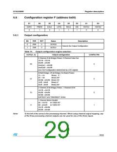
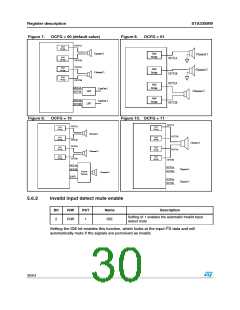
Figure 7.
OCFG = 00 (default value)
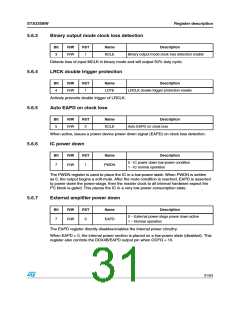
Figure 8.
OCFG = 01
OUT1A
Half
Bridge
Channel 1
Channel 2
Half
Bridge
Channel 1
Channel 2
Half
OUT1A
Bridge
OUT1B
OUT2A
Half
Half
Bridge
Bridge
OUT1B
OUT2A
Half
Bridge
OUT2B
Half
OUT3A
OUT3B
Bridge
LineOut 1
Channel 3
LPF
LPF
Half
Bridge
OUT4A
OUT4B
LineOut 2
OUT2B
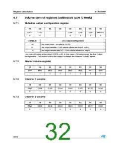
Figure 9.
OCFG = 10
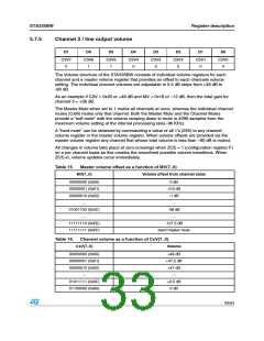
Figure 10. OCFG = 11
OUT1A
OUT1A
Half
Half
Bridge
Bridge
Channel 1
OUT1B
Half
Half
Bridge
Bridge
OUT1B
Channel 3
OUT2A
Half
Bridge
Half
Bridge
OUT2A
OUT2B
Channel 2
Half
Bridge
Half
Bridge
OUT2B
OUT3A
OUT3B
OUT3A
OUT3B
Channel 1
Channel 2
Power
Device
Channel 3
EAPD
OUT4A
OUT4B
5.6.2
Invalid input detect mute enable
Bit
R/W
RST
Name
Description
Setting of 1 enables the automatic invalid input
detect mute
2
R/W
1
IDE
2
Setting the IDE bit enables this function, which looks at the input I S data and will
automatically mute if the signals are perceived as invalid.
30/54

 STMICROELECTRONICS [ ST ]