STA326
at the input data to each processing channel after the channel-mapping block. If any channel receives
2048 consecutive zero value samples (regardless of fs) then that individual channel is muted if this func-
tion is enabled.
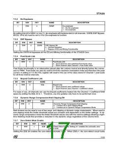
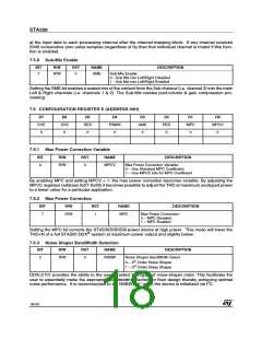
7.5.8 Sub-Mix Enable
BIT
R/W
RST
NAME
DESCRIPTION
7
R/W
0
SME
Sub-Mix Enable:
0 - Sub Mix into Left/Right Disabled
1 - Sub Mix into Left/Right Enabled
Setting the SME bit enables a scaled-mix of the content from the Sub channel (i.e. channel 3) into the main
Left & Right channels (i.e. channels 1 & 2). The Sub-Mix resides post-volume & gain compression pro-
cessing.
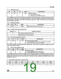
7.6 CONFIGURATION REGISTER E (ADDRESS 04H)
D7
SVE
0
D6
ZCE
0
D5
RES
0
D4
PWMS
0
D3
AME
0
D2
RES
0
D1
MPC
0
D0
MPCV
0
7.6.1 Max Power Correction Variable
BIT
R/W
RST
NAME
DESCRIPTION
0
R/W
0
MPCV
Max Power Correction Variable:
0 – Use Standard MPC Coefficient
1 – Use MPCC bits for MPC Coefficient
By enabling MPC and setting MPCV = 1, the max power correction becomes variable. By adjusting the
MPCC registers (address 0x27-0x28) it becomes possible to adjust the THD at maximum unclipped power
to a lower value for a particular application.
7.6.2 Max Power Correction
BIT
R/W
RST
NAME
DESCRIPTION
Max Power Correction:
7
R/W
1
MPC
0 – MPC Disabled
1 – MPC Enabled
Setting the MPC bit corrects the STA500/505/508 power device at high power. This mode will lower the
THD+N of a full STA500 DDX® system at maximum power output and slightly below.
7.6.3 Noise Shaper BandWidth Selection
BIT
R/W
RST
NAME
DESCRIPTION
Noise Shaper BandWidth Select
2
R/W
0
NSBW
0 – 4th Order Noise Shaper
1 – 3rd Order Noise Shaper
DDXi-2101 provides the ability to the user to select two types of noise-shaper order. This facilitates the
user to essentially make the appropriate bandwidth selection for their design thereby achieving optimal
noise performance. It is recommended to set NSBW = '1' when the device is initialized via I2C.
18/43

 STMICROELECTRONICS [ ST ]