MULTIPROTOCOL SERIAL COMMUNICATIONS INTERFACE (SCI-M)
MULTIPROTOCOL SERIAL COMMUNICATIONS INTERFACE (Cont’d)
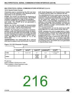
10.5.5 Serial Frame Format
Characters sent or received by the SCI can have
some or all of the features in the following format,
depending on the operating mode:
both Serial Expansion and Asynchronous modes
to indicate that the data is an address (bit set).
The ADDRESS/9TH bit is useful when several mi-
crocontrollers are exchanging data on the same
serial bus. Individual microcontrollers can stay idle
on the serial bus, waiting for a transmitted ad-
dress. When a microcontroller recognizes its own
address, it can begin Data Reception, likewise, on
the transmit side, the microcontroller can transmit
another address to begin communication with a
different microcontroller.
START: the START bit indicates the beginning of
a data frame in Asynchronous modes. The START
condition is detected as a high to low transition.
A dummy START bit is generated in Serial Expan-
sion mode. The START bit is not generated in
Synchronous mode.
DATA: the DATA word length is programmable
from 5 to 8 bits, for both Synchronous and Asyn-
chronous modes. LSB are transmitted first.
The ADDRESS/9TH bit can be used as an addi-
tional data bit or to mark control words (9th bit).
PARITY: The Parity Bit (not available in Serial Ex-
pansion mode and Synchronous mode) is option-
al, and can be used with any word length. It is used
for error checking and is set so as to make the total
number of high bits in DATA plus PARITY odd or
even, depending on the number of “1”s in the
DATA field.
STOP: Indicates the end of a data frame in Asyn-
chronous modes. A dummy STOP bit is generated
in Serial Expansion mode. The STOP bit can be
programmed to be 1, 1.5, 2, 2.5 or 3 bits long, de-
pending on the mode. It returns the SCI to the qui-
escent marking state (i.e., a constant high-state
condition) which lasts until a new start bit indicates
an incoming word. The STOP bit is not generated
in Synchronous mode.
ADDRESS/9TH: The Address/9th Bit is optional
and may be added to any word format. It is used in
Figure 110. SCI Character Formats
(2)
(1)
(3)
(2)
(2)
START
DATA
PARITY
ADDRESS
STOP
1, 1.5, 2, 2.5,
1, 2, 3
16X
1X
# bits
1
5, 6, 7, 8
0, 1
0, 1
NONE
ODD
EVEN
ON
OFF
states
(1)
LSB First
(2)
(3)
Not available in Synchronous mode
Not available in Serial Expansion mode
and Synchronous mode
216/426
9

 STMICROELECTRONICS [ ST ]