ST6208C/ST6209C/ST6210C/ST6220C
CLOCK AND TIMING CHARACTERISTICS (Cont’d)
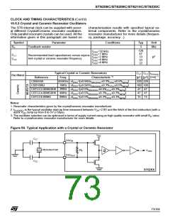
10.5.3 Crystal and Ceramic Resonator Oscillators
The ST6 internal clock can be supplied with sever-
al different Crystal/Ceramic resonator oscillators.
Only parallel resonant crystals can be used. All the
information given in this paragraph are based on
characterization results with specified typical ex-
ternal components. Refer to the crystal/ceramic
resonator manufacturer for more details (frequen-
cy, package, accuracy...).
Symbol
Parameter
Conditions
Typ
Unit
R
Feedback resistor
3
MΩ
F
120
47
33
33
22
f
f
f
f
f
=32 kHz,
OSC
OSC
OSC
OSC
OSC
=1 MHz
=2 MHz
=4 MHz
=8 MHz
C
C
Recommended load capacitances versus equiva-
lent crystal or ceramic resonator frequency
L1
L2
pF
Typical Crystal or Ceramic Resonators
C
C
L2
t
L1
SU(osc)
1)
Oscillator
1)
[ms]
[pF] [pF]
220 220
100 100
47 47
47 47
15 15
Reference
CSB455E
Freq.
455KHz
1MHz
2MHz
4MHz
8MHz
Characteristic
∆f
∆f
∆f
∆f
∆f
=[±0.5KHz
=[±0.5KHz
,±0.3% ,±0.5%
]
]
OSC
OSC
OSC
OSC
OSC
tolerance
∆Ta
aging
CSB1000J
,±0.3% ,±0.5%
∆Ta
tolerance
aging
CSTCC2.00MG0H6
CSTCC4.00MG0H6
CSTCC8.00MG
=[±0.5%
=[±0.5%
=[±0.5%
,±0.5% ,±0.3%
]
]
]
tolerance
tolerance
tolerance
∆Ta
aging
aging
aging
,±0.3% ,±0.3%
∆Ta
,±0.3% ,±0.3%
∆Ta
Notes:
1. Resonator characteristics given by the crystal/ceramic resonator manufacturer.
2. t is the typical oscillator start-up time measured between V =2.8V and the fetch of the first instruction (with a
SU(OSC)
DD
quick V ramp-up from 0 to 5V (<50µs).
DD
3. The oscillator selection can be optimized in terms of supply current using an high quality resonator with small R value.
S
Refer to crystal/ceramic resonator manufacturer for more details.
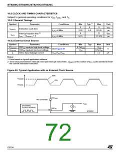
Figure 50. Typical Application with a Crystal or Ceramic Resonator
V
DD
C
L1
OSC
IN
RESONATOR
R
F
F
OSC
OSC
OUT
C
L2
ST62XX
73/104
1

 STMICROELECTRONICS [ ST ]