SM15TY
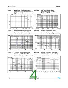
Figure 9.
Characteristics
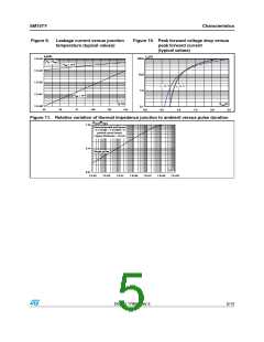
Leakage current versus junction
temperature (typical values)
Figure 10. Peak forward voltage drop versus
peak forward current
(typical values)
IR(nA)
IFM(A)
100.0
1.E+04
1.E+03
1.E+02
1.E+01
1.E+00
VR = VRM
VRM < 10 V
10.0
T = 125 °C
j
T = 25 °C
j
1.0
0.1
V
RM ≥ 10 V
Tj(°C)
150
VFM(V)
2.5
25
50
75
100
125
0.0
0.5
1.0
1.5
2.0
Figure 11. Relative variation of thermal impedance junction to ambient versus pulse duration
Zth(j-a)/Rth(j-a)
1.00
Recommended pad layout
printed circuit board,
copper thickness = 35 µm
0.10
Single pulse
tp(s)
1.E+03
0.01
1.E-03
1.E-02
1.E-01
1.E+00
1.E+01
1.E+02
Doc ID 17865 Rev 3
5/12

 STMICROELECTRONICS [ ST ]