SG2525A-SG3525A
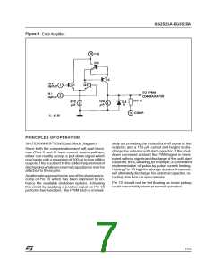
Figure 5
: Error Amplifier.
PRINCIPLES OF OPERATION
SHUTDOWN OPTIONS(see Block Diagram)
ately set providing the fastest turn-off signal to the
outputs ; and a 150 µA current sink begins to dis-
chargethe external soft-start capacitor. If the shut-
down command is short, the PWM signal is termi-
nated without significant discharge of the soft-start
capacitor,thus,allowing, for example,a convenient
implementation of pulse-by-pulse current limiting.
Holding Pin 10 high for a longerduration,however,
will ultimately discharge this external capacitor, re-
cycling slow turn-on upon release.
Since both the compensation and soft-start termi-
nals (Pins 9 and 8) have current source pull-ups,
either can readily accept a pull-down signal which
onlyhas tosinka maximumof 100µA to turnoff the
outputs.This is subjecttothe added requirementof
discharging whateverexternal capacitancemay be
attachedto thesepins.
An alternateapproachisthe useoftheshutdowncir-
cuitry of Pin 10 which has been improved to en-
hance the available shutdown options. Activating
this circuit by applying a positive signal on Pin 10
performs two functions : the PWM latch is immedi-
Pin 10 should not be left floating as noise pickup
could conceivablyinterrupt normal operation.
7/12

 STMICROELECTRONICS [ ST ]