powerSTEP01
Programming manual
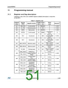
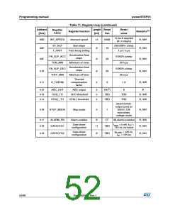
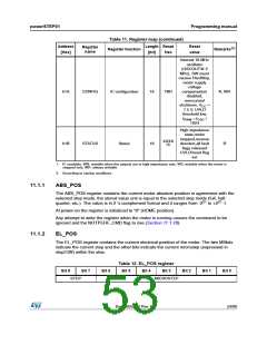
Table 11. Register map (continued)
Address
Length Reset
Reset
Register
name
Register function
Remarks(1)
value
[Hex]
[bit]
Hex
Internal 16 MHz
oscillator
(OSCOUT@ 2
MHz), SW event
causes HardStop,
motor supply
voltage
h1A
CONFIG
IC configuration
16
TBD
compensation
R, WH
disabled,
overcurrent
shutdown, VCC
7.5 V, UVLO
=
threshold low,
fPWM = fOSC
1024
/
High impedance
state,motor
stopped,reverse
direction,all fault
flags released
UVLO/reset flag
set
XXXX
h1B
STATUS
Status
16
R
(2)
1. R: readable, WH: writable when the outputs are in high impedance only, WS: writable when the motor is
stopped only, WR: always writable.
2. According to startup conditions.
11.1.1
11.1.2
ABS_POS
The ABS_POS register contains the current motor absolute position in agreement with the
selected step mode; the stored value unit is equal to the selected step mode (full, half,
quarter, etc.). The value is in 2 's complement format and it ranges from -221 to +221-1.
At power-on the register is initialized to “0” (HOME position).
Any attempt to write the register when the motor is running causes the command to be
ignored and the NOTPERF_CMD flag to rise (Section 11.1.28).
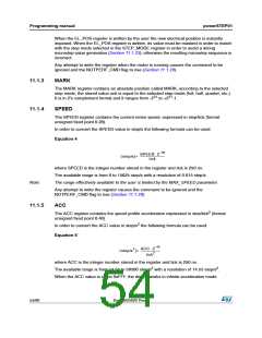
EL_POS
The EL_POS register contains the current electrical position of the motor. The two MSbits
indicate the current step and the other bits indicate the current microstep (expressed in
step/128) within the step.
Table 12. EL_POS register
Bit 8
Bit 7
Bit 6
Bit 5
Bit 4
Bit 3
Bit 2
Bit 1
Bit 0
STEP
MICROSTEP
DocID025022 Rev 1
53/90

 STMICROELECTRONICS [ ST ]