powerSTEP01
Serial interface
10
Serial interface
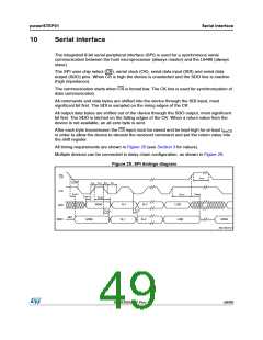
The integrated 8-bit serial peripheral interface (SPI) is used for a synchronous serial
communication between the host microprocessor (always master) and the L6480 (always
slave).
The SPI uses chip select (CS), serial clock (CK), serial data input (SDI) and serial data
output (SDO) pins. When CS is high the device is unselected and the SDO line is inactive
(high impedance).
The communication starts when CS is forced low. The CK line is used for synchronization of
data communication.
All commands and data bytes are shifted into the device through the SDI input, most
significant bit first. The SDI is sampled on the rising edges of the CK.
All output data bytes are shifted out of the device through the SDO output, most significant
bit first. The SDO is latched on the falling edges of the CK. When a return value from the
device is not available, an all zero byte is sent.
After each byte transmission the CS input must be raised and be kept high for at least tdisCS
in order to allow the device to decode the received command and put the return value into
the shift register.
All timing requirements are shown in Figure 25 (see Section 3 for values).
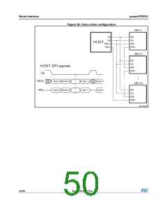
Multiple devices can be connected in daisy chain configuration, as shown in Figure 26.
Figure 25. SPI timings diagram
CS
t
disCS
t
setCS
t
rCK
t
hCK
t
fCK
t
lCK
CK
SDI
t
enSDO
t
disSDO
t
holCS
t
setSDI
t
holSDI
MSB
N-1
N-1
N-2
N-2
LSB
t
vSDO
t
holSDO
HiZ
SDO
MSB
LSB
MSB
AM12837v1
DocID025022 Rev 1
49/90

 STMICROELECTRONICS [ ST ]