powerSTEP01
Functional description
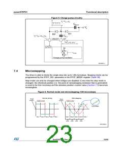
Figure 5. Charge pump circuitry
VS+ VCP
VD1
C
BOOT
VS
D1
D2
VS+ VCP
VD2
C
VD1
FLY
VBOOT
CP
VCP
to high-side
gate drivers
VDD
fPUMP
Charge pump oscillator
AM12827v1
7.4
Microstepping
The driver is able to divide the single step into up to 128 microsteps. Stepping mode can be
programmed by the STEP_SEL parameter in the STEP_MODE register (Table 26).
Step mode can only be changed when bridges are disabled. Every time the step mode is
changed, the electrical position (i.e. the point of microstepping sinewave that is generated)
is reset to the first microstep and the absolute position counter value (Section 7.5) becomes
meaningless.
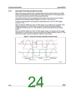
Figure 6. Normal mode and microstepping (128 microsteps)
Normal driving
PHASE A current
PHASE B current
Microstepping
PHASE A current
PHASE B current
Reset
position
Reset
position
microsteps
step 1 step 2 step 3 step 4 step 1
step 1 step 2 step 3 step 4 step 1
128
μsteps
128
μsteps
128
μsteps
128
μsteps
AM12828v1
DocID025022 Rev 1
23/90

 STMICROELECTRONICS [ ST ]