PDF
最近搜索
热门搜索
发布采购

| 型号: | P10NK60ZFP |
| PDF下载: | 下载PDF文件 查看货源 |
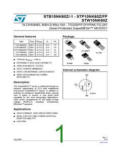
| 内容描述: | N沟道600V - 0.65OHM - 10A - I2 / D2PAK - TO- 220 / FP - TO- 247齐纳保护超网TM功率MOSFET [N-channel 600V - 0.65OHM - 10A - I2/D2PAK - TO-220/FP - TO-247 Zener-protected SuperMESH TM Power MOSFET] |
| 分类和应用: | |
| 文件页数/大小: | 19 页 / 409 K |
| 品牌: |  STMICROELECTRONICS [ ST ] STMICROELECTRONICS [ ST ] |
专业IC领域供求交易平台:提供全面的IC Datasheet资料和资讯,Datasheet 1000万数据,IC品牌1000多家。