L6599
Pin Settings
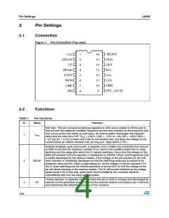
Table 1.
Pin functions
Minimum oscillator frequency setting. This pin provides a precise 2V reference and a resistor
connected from this pin to GND defines a current that is used to set the minimum oscillator
frequency. To close the feedback loop that regulates the converter output voltage by
modulating the oscillator frequency, the phototransistor of an optocoupler will be connected
to this pin through a resistor. The value of this resistor will set the maximum operating
frequency. An R-C series connected from this pin to GND sets frequency shift at start-up to
prevent excessive energy inrush (soft-start).
4
5
RFmin
Burst-mode operation threshold. The pin senses some voltage related to the feedback
control, which is compared to an internal reference (1.25V). If the voltage on the pin is lower
than the reference, the IC enters an idle state and its quiescent current is reduced. The chip
restarts switching as the voltage exceeds the reference by 50mV. Soft-start is not invoked.
This function realizes burst-mode operation when the load falls below a level that can be
programmed by properly choosing the resistor connecting the optocoupler to pin RFmin (see
block diagram). Tie the pin to RFmin if burst-mode is not used.
STBY
Current sense input. The pin senses the primary current though a sense resistor or a
capacitive divider for lossless sensing. This input is not intended for a cycle-by-cycle control;
hence the voltage signal must be filtered to get average current information. As the voltage
exceeds a 0.8V threshold (with 50mV hysteresis), the soft-start capacitor connected to pin 1
is internally discharged: the frequency increases hence limiting the power throughput. Under
output short circuit, this normally results in a nearly constant peak primary current. This
condition is allowed for a maximum time set at pin 2. If the current keeps on building up
despite this frequency increase, a second comparator referenced at 1.5V latches the device
off and brings its consumption almost to a “before start-up” level. The information is latched
and it is necessary to recycle the supply voltage of the IC to enable it to restart: the latch is
removed as the voltage on the Vcc pin goes below the UVLO threshold. Tie the pin to GND if
the function is not used.
6
ISEN
Line sensing input. The pin is to be connected to the high-voltage input bus with a resistor
divider to perform either AC or DC (in systems with PFC) brownout protection. A voltage
below 1.25V shuts down (not latched) the IC, lowers its consumption and discharges the
soft-start capacitor. IC’s operation is re-enabled (soft-started) as the voltage exceeds 1.25V.
The comparator is provided with current hysteresis: an internal 15µA current generator is ON
as long as the voltage applied at the pin is below 1.25V and is OFF if this value is exceeded.
Bypass the pin with a capacitor to GND to reduce noise pick-up. The voltage on the pin is
top-limited by an internal zener. Activating the zener causes the IC to shut down (not
latched). Bias the pin between 1.25 and 6V if the function is not used.
7
8
LINE
Latched device shutdown. Internally the pin connects a comparator that, when the voltage
on the pin exceeds 1.85V, shuts the IC down and brings its consumption almost to a “before
start-up” level. The information is latched and it is necessary to recycle the supply voltage of
the IC to enable it to restart: the latch is removed as the voltage on the VCC pin goes below
the UVLO threshold. Tie the pin to GND if the function is not used.
DIS
Open-drain ON/OFF control of PFC controller. This pin, normally open, is intended for
stopping the PFC controller, for protection purpose or during burst-mode operation. It goes
low when the IC is shut down by DIS > 1.85V, ISEN > 1.5V, LINE > 6V and STBY < 1.25V.
The pin is pulled low also when the voltage on pin DELAY exceeds 2V and goes back open
as the voltage falls below 0.3V. During UVLO, it is open. Leave the pin unconnected if not
used.
9
PFC_STOP
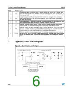
GND
Chip ground. Current return for both the low-side gate-drive current and the bias current of
the IC. All of the ground connections of the bias components should be tied to a track going
to this pin and kept separate from any pulsed current return.
10
5/36

 STMICROELECTRONICS [ ST ]