L6599
Application information
7.4
Current sense, OCP and OLP
The resonant half-bridge is essentially voltage-mode controlled; hence a current sense input
will only serve as an overcurrent protection (OCP).
Unlike PWM-controlled converters, where energy flow is controlled by the duty cycle of the
primary switch (or switches), in a resonant half-bridge the duty cycle is fixed and energy flow
is controlled by its switching frequency. This impacts on the way current limitation can be
realized. While in PWM-controlled converters energy flow can be limited simply by
terminating switch conduction beforehand when the sensed current exceeds a preset
threshold (this is commonly now as cycle-by-cycle limitation), in a resonant half-bridge the
switching frequency, that is, its oscillator's frequency must be increased and this cannot be
done as quickly as turning off a switch: it takes at least the next oscillator cycle to see the
frequency change. This implies that to have an effective increase, able to change the energy
flow significantly, the rate of change of the frequency must be slower than the frequency
itself. This, in turn, implies that cycle-by-cycle limitation is not feasible and that, therefore,
the information on the primary current fed to the current sensing input must be somehow
averaged. Of course, the averaging time must not be too long to prevent the primary current
from reaching too high values.
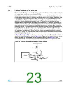
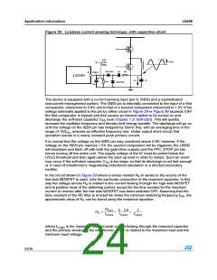
In Figure 29 and Figure 30 a couple of current sensing methods are illustrated that will be
described in the following. The circuit of Figure 29 is simpler but the dissipation on the sense
resistor Rs might not be negligible, hurting efficiency; the circuit of Figure 30 is more
complex but virtually lossless and recommended when the efficiency target is very high.
Figure 29. Current sensing technique with sense resistor
Cr
6
ISEN
6
ICr
L6599
L6599
10
fmin
Vspk
0
Rs
τ ≈
23/36

 STMICROELECTRONICS [ ST ]