L6562A
Electrical characteristics
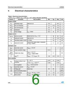
Table 5. Electrical characteristics (continued)
( -25°C < TJ < +125°C, VCC = 12V, Co = 1nF; unless otherwise specified)
Symbol
Parameter
Test condition
SOURCE = 0.5mA
Min
Typ
Max
Unit
I
Upper clamp voltage
5.3
5.7
6
V
VCOMP
ISINK = 0.5mA (1)
Lower clamp voltage
Disable threshold
Restart threshold
2.1
150
380
2.25
200
450
2.4
250
520
V
VINVdis
VINVen
mV
mV
Output overvoltage
Dynamic OVP triggering
current
IOVP
Hys
23.5
2.1
27
30.5
2.4
µA
(3)
(1)
Hysteresis
20
µA
V
Static OVP threshold
2.25
Current sense comparator
ICS
tLEB
VCS = 0
Input bias current
Leading edge blanking
Delay to output
-1
µA
ns
ns
V
100
1.0
200
175
1.08
25
300
td(H-L)
VCS
VCOMP = Upper clamp, Vmult = 1.5V
Current sense clamp
1.16
VMULT = 0
Vcsoffset
Current sense offset
mV
VMULT = 2.5V
5
Zero current detector
VZCDH
VZCDL
IZCD = 2.5mA
Upper clamp voltage
Lower clamp voltage
5.0
5.7
0
6.5
0.3
V
V
IZCD = - 2.5mA
-0.3
Arming voltage
(positive-going edge)
(3)
VZCDA
1.4
V
V
Triggering voltage
(negative-going edge)
VZCDT
(3)
0.7
2
IZCDb
IZCDsrc
IZCDsnk
VZCD = 1 to 4.5V
Input bias current
µA
mA
mA
Source current capability
Sink current capability
-2.5
2.5
Starter
tSTART
Start timer period
75
190
300
µs
7/26

 STMICROELECTRONICS [ ST ]