Electrical characteristics
L6562A
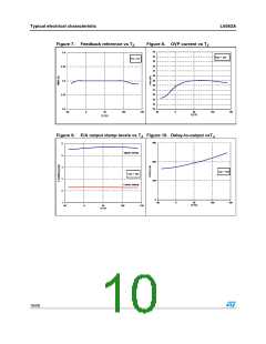
5
Electrical characteristics
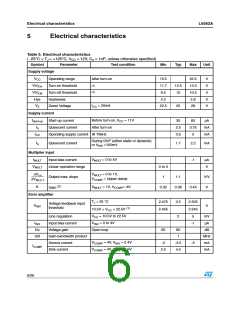
Table 5. Electrical characteristics
( -25°C < TJ < +125°C, VCC = 12V, Co = 1nF; unless otherwise specified)
Symbol
Parameter
Test condition
Min
Typ
Max
Unit
Supply voltage
VCC
Operating range
Turn-on threshold
Turn-off threshold
Hysteresis
After turn-on
10.5
11.7
9.5
22.5
13.3
10.5
2.8
V
V
V
V
V
VccOn
VccOff
(1)
(1)
12.5
10
Hys
VZ
2.2
ICC = 20mA
Zener Voltage
22.5
25
28
Supply current
Istart-up
Iq
Before turn-on, VCC = 11V
After turn-on
Start-up current
30
2.5
3.5
60
3.75
5
µA
mA
mA
Quiescent current
ICC
Operating supply current @ 70kHz
During OVP (either static or dynamic)
Iq
Quiescent current
1.7
2.2
mA
or VINV ≤150mV
Multiplier input
IMULT
VMULT = 0 to 4V
Input bias current
-1
µA
V
VMULT
Linear operation range
0 to 3
1
∆Vcs
VMULT = 0 to 1V,
VCOMP = Upper clamp
---------------------
∆VMULT
Output max. slope
Gain (2)
1.1
V/V
V
K
VMULT = 1V, VCOMP= 4V,
0.32
0.38
0.44
Error amplifier
TJ = 25 °C
2.475
2.455
2.5
2
2.525
2.545
5
Voltage feedback input
threshold
VINV
V
10.5V < VCC < 22.5V (1)
VCC = 10.5V to 22.5V
VINV = 0 to 3V
Line regulation
mV
IINV
Input bias current
Voltage gain
-1
µA
dB
Gv
Open loop
60
80
1
GB
Gain-bandwidth product
Source current
MHz
mA
VCOMP = 4V, VINV = 2.4V
-2
-3.5
-5
ICOMP
VCOMP = 4V, VINV = 2.6V
Sink current
2.5
4.5
mA
6/26

 STMICROELECTRONICS [ ST ]