L6205
PARALLELED OPERATION
The outputs of the L6205 can be paralleled to increase the output current capability or reduce the power dissi-
pation in the device at a given current level. It must be noted, however, that the internal wire bond connections
from the die to the power or sense pins of the package must carry current in both of the associated half bridges.
When the two halves of one full bridge (for example OUT1 and OUT2 ) are connected in parallel, the peak
A
A
current rating is not increased since the total current must still flow through one bond wire on the power supply
or sense pin. In addition, the over current detection senses the sum of the current in the upper devices of each
bridge (A or B) so connecting the two halves of one bridge in parallel does not increase the over current detec-
tion threshold.
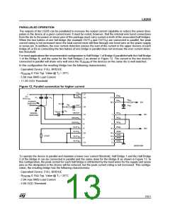
For most applications the recommended configuration is Half Bridge 1 of Bridge A paralleled with the Half Bridge
1 of the Bridge B, and the same for the Half Bridges 2 as shown in Figure 12. The current in the two devices
connected in parallel will share very well since the R
of the devices on the same die is well matched.
DS(ON)
In this configuration the resulting Bridge has the following characteristics.
- Equivalent Device: FULL BRIDGE
- R
0.15Ω Typ. Value @ T = 25°C
J
DS(ON)
- 5.6A max RMS Load Current
- 11.2A OCD Threshold
Figure 12. Parallel connection for higher current
VSA
+
VS
8-52VDC
17
ENB
ENA
VSB
C1
C2
14
19
11
20
REN
CEN
POWER
GROUND
-
EN
D1
RP
VCP
CP
D2
CBOOT
VBOOT
IN1A
IN2A
IN1B
IN2B
SIGNAL
GROUND
12
3
1
2
IN1
IN2
SENSEA
SENSEB
OUT1A
OUT2A
OUT1B
OUT2B
8
9
4
10
GND
GND
GND
GND
18
7
16
15
6
LOAD
13
5
D02IN1359
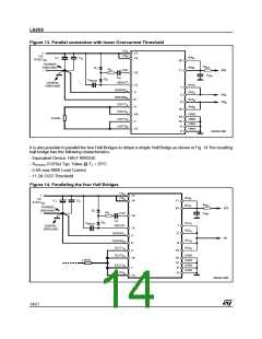
To operate the device in parallel and maintain a lower over current threshold, Half Bridge 1 and the Half Bridge
2 of the Bridge A can be connected in parallel and the same done for the Bridge B as shown in Figure 13. In
this configuration, the peak current for each half bridge is still limited by the bond wires for the supply and sense
pins so the dissipation in the device will be reduced, but the peak current rating is not increased. This configu-
ration, the resulting bridge has the following characteristics.
- Equivalent Device: FULL BRIDGE
- R
0.15Ω Typ. Value @ TJ = 25°C
DS(ON)
- 2.8A max RMS Load Current
- 5.6A OCD Threshold
13/21

 STMICROELECTRONICS [ ST ]