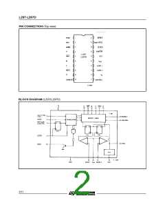
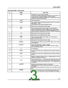
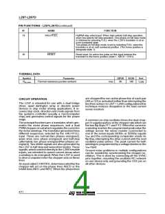
L297-L297D
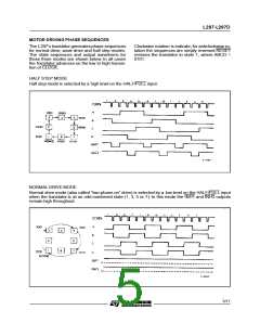
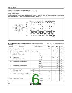
MOTOR DRIVING PHASE SEQUENCES (continued)
WAVE DRIVE MODE
Wave drive mode (also called ”one-phase-on” drive) is selected by a low level on the HALF/FULL input
when the translator is at an even numbered state (2, 4, 6 or 8).
(Refer to the block diagram T
= 25 C, V = 5V unless otherwise
°
s
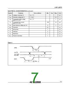
ELECTRICAL CHARACTERISTICS
specified)
amb
Symbol
Parameter
Test conditions
Min.
Typ
Max.
7
Unit
V
Vs
Is
Supply voltage (pin 12)
4.75
Quiescent supply current (pin 12)
Outputs floating
50
80
mA
V
Vi
Input voltage
(pin 11, 17, 18, 19, 20)
Low
0.6
Vs
High
2
V
Input current
(pin 11, 17, 18, 19, 20)
Ii
Vi = L
Vi = H
Low
100
µ
A
10
1.3
Vs
A
µ
Ven
Enable input voltage (pin 10)
Enable input current (pin 10)
V
High
2
V
Ien
Ven = L
Ven = H
VOL
100
10
µ
A
A
µ
Vo
Phase output voltage
(pins 4, 6, 7, 9)
Io = 10mA
Io = 5mA
Io = 10mA
Io = 5mA
Io = 5mA
Io = 5mA
0.4
V
VOH
3.9
V
V
V
V
Vinh
Inhibit output voltage (pins 5, 8)
Sync OutputVoltage
Vinh L
Vinh H
VSYNC H
VSYNC V
0.4
0.8
3.9
3.3
VSYNC
6/11

 STMICROELECTRONICS [ ST ]