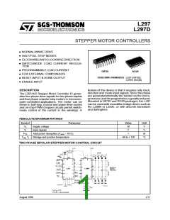
L297-L297D
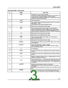
PIN FUNCTIONS - L297/L297D(continued)
N°
NAME
FUNCTION
19
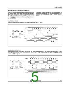
HALF/FULL
Half/full step select input. When high selects half step operation,
when low selects full step operation. One-phase-on full step mode
is obtained by selecting FULL when the L297’s translator is at an
even-numbered state.
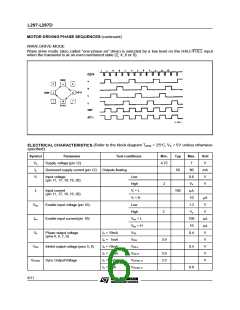
Two-phase-on full step mode is set by selecting FULL when the
translator is at an odd numbered position. (The home position is
designate state 1).
20
RESET
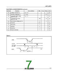
Reset input. An active low pulse on this input restores the
translator to the home position (state 1, ABCD = 0101).
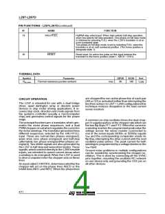
THERMAL DATA
Symbol
Parameter
Thermal resistance junction-ambient
DIP20
SO20
Unit
Rth-j-amb
max
80
100
°
C/W
are choppedthe non-activephase line of each pair
(AB or CD)is activated(ratherthan interruptingthe
line then active).In L297 + L298 configurationsthis
technique reduces dissipation in the load current
sense resistors.
CIRCUIT OPERATION
The L297 is intended for use with a dual bridge
driver, quad darlington array or discrete power
devices in step motor driving applications. It re-
ceives step clock, direction and mode signals from
the systems controller (usually a microcomputer
chip) and generates control signals for the power
stage.
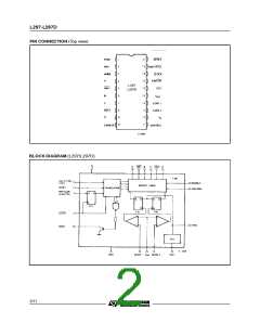
The principal functionsare a translator,which gen-
erates the motor phase sequences, and a dual
PWMchoppercircuit which regulatesthe currentin
the motor windings.The translator generatesthree
different sequences, selected by the HALF/FULL
input. These are normal (two phases energised),
wave drive (one phase energised) and half-step
(alternately one phase energised/two phases en-
ergised).Two inhibit signals are also generated by
the L297 in half stepand wavedrivemodes.These
signals, whichconnectdirectlyto the L298’senable
inputs, are intended to speed current decay when
a winding is de-energised.When the L297 is used
to drivea unipolarmotor the chopper acts on these
lines.
A common on-chip oscillator drives the dual chop-
per.It suppliespulses at thechopperratewhich set
the two flip-flops FF1 and FF2.Whenthe current in
a winding reaches the programmed peakvalue the
voltage across the sense resistor (connected to
one of the sense inputs SENS1 or SENS2) equals
Vref and the corresponding comparator resets its
flip flop, interrupting the drive current until the next
oscillator pulse arrives. The peak current for both
windingsis programmedbya voltagedivideron the
Vref input.
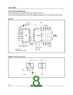
Ground noise problems in multiple configurations
can be avoided by synchronising the chopper os-
cillators. This is done by connecting all the SYNC
pins together, mounting the oscillator RC network
on one device only and grounding the OSC pin on
all other devices.
An inputcalled CONTROL determines whetherthe
chopper will act on the phase lines ABCD or the
inhibit lines INH1 and INH2. When the phase lines
4/11

 STMICROELECTRONICS [ ST ]